


مقدمه:
در مقاله زیر بطور کامل سیستم ارتینگ و گراند توضیح داده شده است مطالب بر اساس آخرین استاندارد روز دنیا تهیه شده و امید است خوانندگان عزیز با مطالعه آن به هر گونه سوال و اشکالی که در زمینه این سیستم بسیار مهم و حیاتی که در حوزه برق دارند پاسخ داده شود و اشکالات مرتفع گردد.

What is Grounding or Earthing?
To connect the metallic (conductive) Parts of an Electric appliance or installations to the earth (ground) is called Earthing or Grounding.
In other words, to connect the metallic parts of electric machinery and devices to the earth plate or earth electrode (which is buried in the moisture earth) through a thick conductor wire (which has very low resistance) for safety purpose is known as Earthing or grounding.
To earth or earthing rather, means to connect the part of electrical apparatus such as metallic covering of metals, earth terminal of socket cables, stay wires that do not carry current to the earth. Earthing can be said as the connection of the neutral point of a power supply system to the earth so as to avoid or minimize danger during discharge of electrical energy.

Good to know
Difference between Earthing, Grounding and Bonding.
Let me clear the confusion among earhing, grounding and bonding.
Earthing and Grounding is the same terms used for earthing. Grounding is the commonly word used for earthing in the North American standards like IEEE, NEC, ANSI and UL etc while, Earthing is used in European, Common wealth countries and Britain standards like IS and IEC etc.
The word Bonding used for jointing two wires (as well as conductors, pipes or appliances together. Bonding is known as connecting the metallic parts of different machines which is not considered to be carrying electric current during normal operation of the machines to bring them at the same level of electric potential.
Need of Earthing or Grounding. Why Earthing is Important?
The primary purpose of earthing is to avoid or minimize the danger of electrocution, fire due to earth leakage of current through undesired path and to ensure that the potential of a current carrying conductor does not rise with respect to the earth than its designed insulation.
When the metallic part of electrical appliances (parts that can conduct or allow passage of electric current) comes in contact with a live wire, maybe due to failure of installations or failure in cable insulation, the metal become charged and static charge accumulates on it. If a person touches such a charged metal, the result is a severe shock.
To avoid such instances, the power supply systems and parts of appliances have to be earthed so as to transfer the charge directly to the earth.
Below are the basic needs of Earthing.
- To protect human lives as well as provide safety to electrical devices and appliances from leakage current.
- To keep voltage as constant in the healthy phase (If fault occurs on any one phase).
- To Protect Electric system and buildings form lighting.
- To serve as a return conductor in electric traction system and communication.
- To avoid the risk of fire in electrical installation systems.
Different Terms used in Electrical Earthing
- Earth: The proper connection between electrical installation systems via conductor to the buried plate in the earth is known as Earth.
- Earthed: When an electrical device, appliance or wiring system connected to the earth through earth electrode, it is known as earthed device or simple “Earthed”.
- Solidly Earthed: When an electric device, appliance or electrical installation is connected to the earth electrode without a fuse, circuit breaker or resistance/Impedance, It is called “solidly earthed”.
- Earth Electrode: When a conductor (or conductive plate) buried in the earth for electrical earthing system. It is known to be Earth Electrode. Earth electrodes are in different shapes like, conductive plate, conductive rod, metal water pipe or any other conductor with low resistance.
- Earthing Lead: The conductor wire or conductive strip connected between Earth electrode and Electrical installation system and devices in called Earthing lead.
- Earth Continuity Conductor: The conductor wire, which is connected among different electrical devices and appliances like, distribution board, different plugs and appliances etc. in other words, the wire between earthing lead and electrical device or appliance is called earth continuity conductor. It may be in the shape of metal pipe (fully or partial), or cable metallic sheath or flexible wire.
- Sub Main Earthing Conductor: A wire connected between switch board and distribution board i.e. that conductor is related to sub main circuits.
- Earth Resistance: This is the total resistance between earth electrode and earth in Ω (Ohms). Earth resistance is the algebraic sum of the resistances of earth continuity conductor, earthing lead, earth electrode and earth.
POINTS TO BE EARTHED
Earthing is not done anyhow. According to IE rules and IEE (Institute of Electrical Engineers) regulations,
- Earth pin of 3-pin lighting plug sockets and 4-pin power plug should be efficiently and permanently earthed.
- All metal casing or metallic coverings containing or protecting any electric supply line or apparatus such as GI pipes and conduits enclosing VIR or PVC cables, iron clad switches, iron clad distribution fuse boards etc should be earthed (connected to earth).
- The frame of every generator, stationary motors and metallic parts of all transformers used for controlling energy should be earthed by two separate and yet distinct connections with the earth.
- In a dc 3-wire system, the middle conductors should be earthed at the generating station.
- Stay wires that are for overhead lines should be connected to earth by connecting at least one strand to the earth wires.
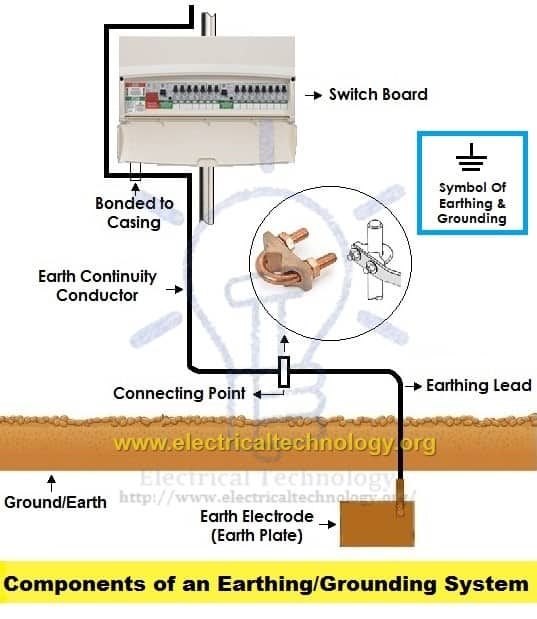
Components of Earthing System
A complete electrical earthing system consists on the following basic components.
- Earth Continuity Conductor
- Earthing Lead
- Earth Electrode
Earth Continuity Conductor or Earth Wire
That part of the earthing system which interconnects the overall metallic parts of electrical installation e.g. conduit, ducts, boxes, metallic shells of the switches, distribution boards, Switches, fuses, Regulating and controlling devices, metallic parts of electrical machines such as, motors, generators, transformers and the metallic framework where electrical devices and components are installed is known as earth wire or earth continuity conductor as shown in the above fig.
The resistance of the earth continuity conductor is very low. According to IEEE rules, resistance between consumer earth terminal and earth Continuity conductor (at the end) should not be increased than 1Ω. In simple words, resistance of earth wire should be less than 1Ω.
Size of the Earth Continuity Conductor or Earth Wire depends on the cable size used in the wiring circuit.
Size of Earth Continuity Conductor
The cross sectional area of the Earth Continuity Conductor should not be less than the half of the cross sectional area of the thickest wire used in the electrical wiring installation.
Generally, the size of the bare copper wire used as earth continuity conductor is 3SWG. But keep in mind that, don’t use less than 14SWG as earth wire. Copper strip is also can be used as earth continuity conductor instead of bare copper wire but don’t go for it until manufacture recommend it.
Earthing Lead or Earthing Joint
The conductor wire connected between earth continuity conductor and earth electrode or earth plate is called earthing joint or “Earthing lead”. The point where earth continuity conductor and earth electrode meet is known as “connecting point” as shown in the above fig.
Earthing lead is the final part of the earthing system which is connected to the earth electrode (which is underground) through earth connecting point.
There should be minimum joints in earthing lead as well as lower in size and straight in the direction.
Generally, copper wire can be used as earthing lead but, copper strip is also used for high installation and it can handle the high fault current because of wider area than the copper wire.
A hard drawn bare copper wire is also used as an earthing lead. In this method, all earth conductors connected to a common (one or more) connecting points and then, earthing lead is used to connect earth electrode (earth plat) to the connecting point.
To increase the safety factor of installation, two copper wires are used as earthing lead to connect the device metallic body to the earth electrode or earth plate. I.e. if we use two earth electrodes or earth plats, there would be four earthing leads. It should not be considered that the two earth leads are used as parallel paths to flow the fault currents but both paths should work properly to carry the fault current because it is important for better safety.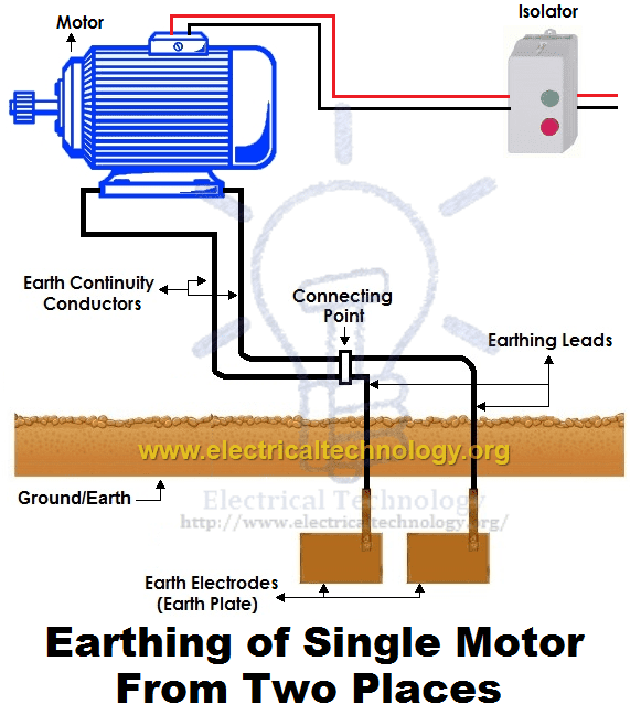
Size of the Earthing Lead
The size or area of earthing lead should not be less than the half of the thickest wire used in the installation.
The largest size for earthing lead is 3SWG and the minimum size should not be less than 8SWG. If 37/.083 wire is used or the load current is 200A from the supply voltage, then it is recommended to use copper strip instead of double earthing lead. The earth lead connection methods is shown in the above fig.
Note: We will post additional article about Earth Plate size with simple calculations… Stay tune.
Earthing Electrode or Earth Plate
A metallic electrode or plate which is buried in the earth (underground) and it is the last part of the electrical earthing system. In simple words, the final underground metallic (plate) part of the earthing system which is connected with earthing lead is called earth plate or earth electrode.
A metallic plate, pipe or rode can be used as an earth electrode which has very low resistance and carry the fault current safely towards ground (earth).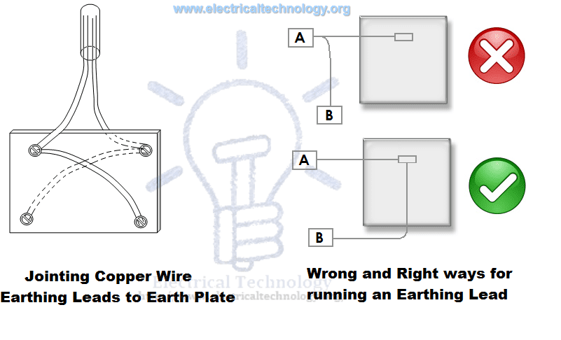 Size of Earthing Electrode
Both copper and iron can be used as earthing electrode.
The size of earth electrode (In case of copper)
۲×۲ (two foot wide as well as in length) and 1/8 inch thickness.. I.e. 2’ x 2’ x 1/8”. (۶۰۰x600x300 mm)
In case of Iron
۲’ x2’ x ¼” = ۶۰۰x600x6 mm
It is recommended to bury the earth electrode in the moisture earth. If it is not possible, then put water in the GI (Galvanized Iron) pipe to make possible the moisture condition.
In the earthing system, put the earth electrode in vertical position (underground) as shown in the above fig. Also, put a 1 foot (about 30cm) layer of powdered charcoal and lime mixture around the earth plate (don’t confuse with earth electrode and earth plate as both are the same thing).
This action makes the possible increase in the size of the earth electrode which leads a better continuity in the earth (earthing system) and also helps to maintain the moisture condition around earth plate.
P.S: We will post Example calculation about Earth Electrode Sizing… Stay tune.
Good to know:Don’t use coke (after burning coal in the furnace to emit all the gases and other components, the remaining 88% carbon is called coke) or stone coal instead of charcoal (wood coal) because it causes to corrosion in the earth plate.
Since, the water level is different in the different areas; therefore, the depth for earth electrode installation is also different in various areas. But, the depth for earth electrode installation should not be less than 10ft (3 meter) and should below 1 foot (304.8mm) from the constant water level.
Motors, Generator, Transformers etc should be connected from to earth electrode two different places.
Earth Plate or Earth Electrode Size for Small installation
In small installation, use metallic rod (diameter = 25mm (1inch) and length = 2m (6ft) instead of earth plate for earthing system. The metallic pipe should be 2 meter below from the surface of ground. To maintain the moister condition, put 25mm (1inch) coal and lime mixture around the earth plate.
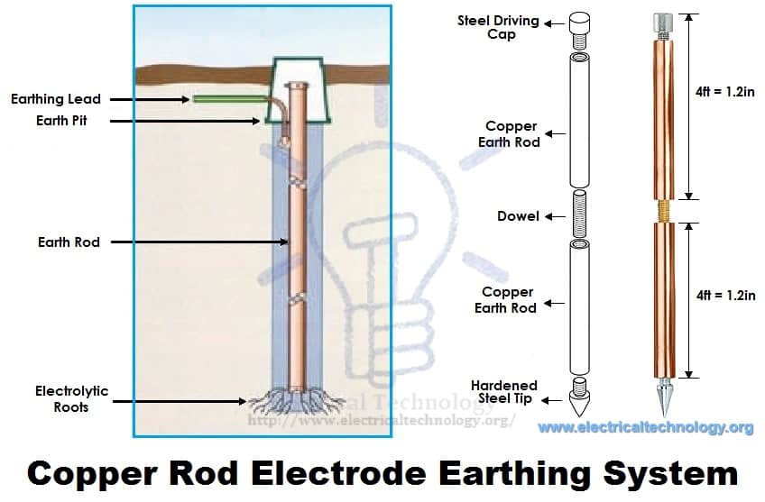
For effectiveness and convenience, you may use the copper rods 12.5mm (0.5 inch) to 25mm (1 inch) diameter and 4m (12ft) length. We will discuss the installation method of rod earthing latter.
Methods of Earthing | Types of Earthing
Earthing can be done in many ways. The various methods employed in earthing (in house wiring or factory and other connected electrical equipment and machines) are discussed as follows:
۱). Plate Earthing:
In plate earthing system, a plate made up of either copper with dimensions 60cm x 60cm x 3.18mm (i.e. 2ft x 2ft x 1/8 in) or galvanized iron (GI) of dimensions 60cm x 60cm x 6.35 mm (2ft x 2ft x ¼ in) is buried vertical in the earth (earth pit) which should not be less than 3m (10ft) from the ground level.
For proper earthing system, follow the above mentioned steps in the (Earth Plate introduction) to maintain the moisture condition around the earth electrode or earth plate.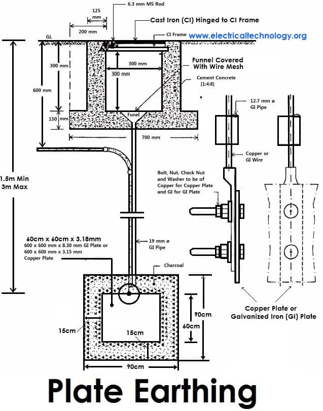
۲). Pipe Earthing:
A galvanized steel and a perforated pipe of approved length and diameter is placed vertically in a wet soil in this kind of system of earthing. It is the most common system of earthing.
The size of pipe to use depends on the magnitude of current and the type of soil. The dimension of the pipe is usually 40mm (1.5in) in diameter and 2.75m (9ft) in length for ordinary soil or greater for dry and rocky soil. The moisture of the soil will determine the length of the pipe to be buried but usually it should be 4.75m (15.5ft).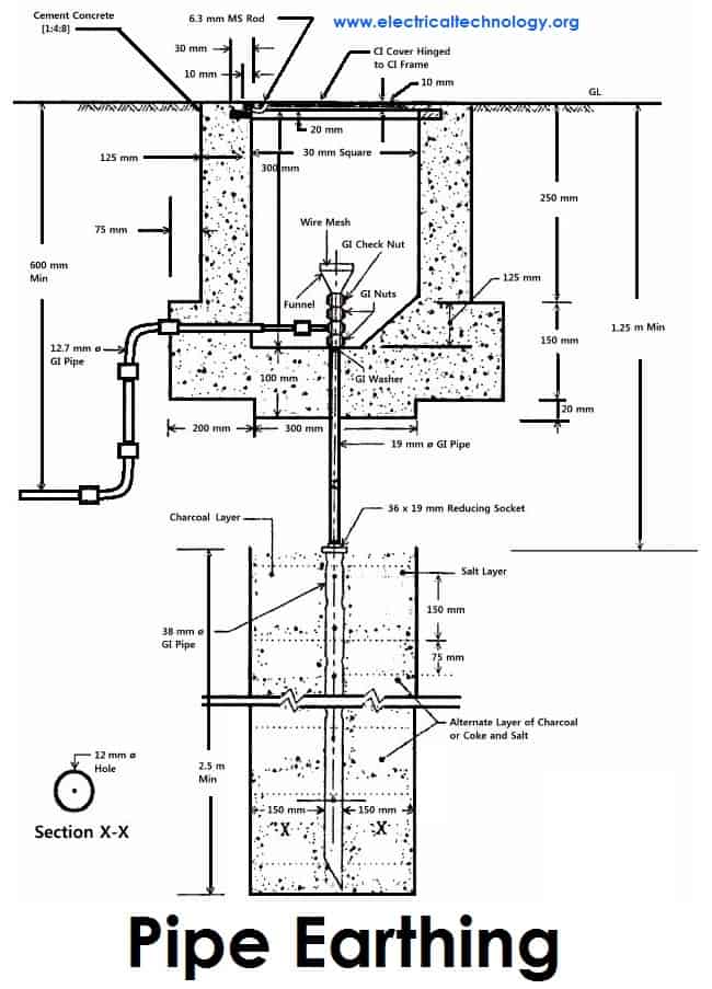
۳). Rod Earthing
it is the same method as pipe earthing. A copper rod of 12.5mm (1/2 inch) diameter or 16mm (0.6in) diameter of galvanized steel or hollow section 25mm (1inch) of GI pipe of length above 2.5m (8.2 ft) are buried upright in the earth manually or with the help of a pneumatic hammer. The length of embedded electrodes in the soil reduces earth resistance to a desired value.
۴). Earthing through the Waterman
In this method of earthing, the waterman (Galvanized GI) pipes are used for earthing purpose. Make sure to check the resistance of GI pipes and use earthing clamps to minimize the resistance for proper earthing connection.
If stranded conductor is used as earth wire, then clean the end of the strands of the wire and make sure it is in the straight and parallel position which is possible then to connect tightly to the waterman pipe.
۵). Strip or Wire Earthing:
In this method of earthing, strip electrodes of cross-section not less than 25mm x 1.6mm (1in x 0.06in) is buried in a horizontal trenches of a minimum depth of 0.5m. If copper with a cross-section of 25mm x 4mm (1in x 0.15in) is used and a dimension of 3.0mm2 if it’s a galvanized iron or steel.
If at all round conductors are used, their cross-section area should not be too small, say less than 6.0mm2 if it’s a galvanized iron or steel. The length of the conductor buried in the ground would give a sufficient earth resistance and this length should not be less than 15m.
General method of Earthing / Proper Grounding Installation (Step by Step)
The usual method of earthing of electric equipments, devices and appliances are as follow:
- First of all, dig a 5x5ft (1.5×۱٫۵m) pit about 20-30ft (6-9 meters) in the ground. (Note that, depth and width depends on the nature and structure of the ground)
- Bury an appropriate (usually 2’ x 2’ x 1/8” (۶۰۰x600x300 mm) copper plate in that pit in vertical position.
- Tight earth lead through nut bolts from two different places on earth plate.
- Use two earth leads with each earth plate (in case of two earth plates) and tight them.
- To protect the joints from corrosion, put grease around it.
- Collect all the wires in a metallic pipe from the earth electrode(s). Make sure the pipe is 1ft (30cm) above the surface of the ground.
- To maintain the moisture condition around the earth plate, put a 1ft (30cm) layer of powdered charcoal (powdered wood coal) and lime mixture around the earth plate of around the earth plate.
- Use thimble and nut bolts to connect tightly wires to the bed plates of machines. Each machine should be earthed from two different places. The minimum distance between two earth electrodes should be 10 ft (3m).
- Earth continuity conductor which is connected to the body and metallic parts of all installation should be tightly connected to earth lead.
- At last (but not least), test the overall earthing system through earth tester. If everything is going about the planning, then fill the pit with soil. The maximum allowable resistance for earthing is 1Ω. If it is more than 1 ohm, then increase the size (not length) of earth lead and earth continuity conductors. Keep the external ends of the pipes open and put the water time to time to maintain the moisture condition around the earth electrode which is important for the better earthing system.
SI specification for Earthing
Various specifications in respect to earthing as recommended by Indian Standards are given below. Here are few;
- An earthing electrode should not be situated (installed) close to the building whose installation system is being earthed at least more than 1.5m away.
- The earth resistance should be low enough to cause the flow of current sufficient to operate the protective relays or blow fuses. It’s value is not constant as it varies with weather because it depends on moisture (but should not be less than 1 Ohm).
- The earth wire and earth electrode will be the same material.
- The earthing electrode should always be placed in a vertical position inside the earth or pit so that it may be in contact with all the different earth layers.
Dangers Of Not Earthing A Supply System
As emphasized on earlier, earthing is provided in order
- To avoid electric shock
- To avoid risk of fire as a result of earth leakage current through unwanted path and
- To ensure that no current carrying conductor rises to a potential with respect to general mass of earth than its designed insulation.
However, if excessive current is not earthed, appliances will be damaged without the help of fuse in place. You should note that excessive current are earthed at their generating stations which is why earth wires carries very little or no current at all. It therefore implies that it is not necessary to earth any of the wires (live, earth and neutral wires) contained in a PVC. Earthing the live wire is catastrophic.
I have seen a person killed simply because a live wire got cut from overhead pole and fell to the ground while the ground was wet. Excessive current is earthed at generating stations and if at all the earthing is not efficient due to fault, earth fault interrupters will be there to help. Fuse help only when the power transmitted is above the rating of our appliances, it blocks the current from reaching our appliances by blowing off and protecting our appliances in the process.
In our electrical appliances, if excessive currents are not earthed, we would experience severe shock. Earthing takes place in electrical appliances only when there is a problem and it is to save us from danger. If in an electronic installation, a metallic part of an electrical appliance comes in direct contact with a live wire that results from maybe failure of installation or otherwise, the metal will be charged and static charge will accumulate on it.
If you happen to touch the metallic part at that moment you will be zapped. But if the metallic part of the appliance is earthed, the charge will be transferred to earth instead of accumulating on the metallic part of the appliance. Current don’t flow through earth wires in electrical appliances, it does so only when there is problem and only to direct the unwanted current to earth in order to protect us from severe shock.
In addition, if a live wire touches accidentally (in a faulty system) to the metallic part of a machine. Now, if a man touches that metallic part of the machine, then the current will flow through their body to the ground, hence, he will get shocked (electrocuted) which may lead to serious injuries even to death. That’s why earthing is so important?
Electrical Grounding & Earthing….. To be continued…
Please subscribe below, if you want to get the upcoming post about Earthing/Grounding such as:
- Calculate the size of Earth Continuity Conductor, Earthing Lead & Earth Electrodes for differnt electrical devices and equipment such motors, transformers, home wiring etc by Simple calculations
- Earthing Circuit and Earth Fault Current
- Protection of Earthing System and Additional devices used in the Earthing / Grounding System
- Points To remember while Providing Grounding / Earthing
- Important Instruction for Proper earthing system
- Electricity rules about Earthing
- How to Test Earth Resistance by Earth Tester
- How to test Earth loop Resistance by Am-Meter & Voltmeter
- Protective Multiple Earthing
Objectives of electrical earthing
Protective earthing
An earth ground connection of the exposed conductive parts of electrical equipment helps protect from electric shock by keeping the exposed conductive surface of connected devices close to earth potential, when a failure of electrical insulation occurs. When a fault occurs, current flows from the power system to earth. The current may be high enough to operate the over current protection fuse or circuit breaker, which will then interrupt the circuit. To ensure the voltage on exposed surfaces is not too high, the impedance (resistance) of the connection to earth must be kept low relative to the normal circuit impedance.
An alternative to protective earthing of exposed surfaces is a design with “double insulation” or other precautions, such that a single failure or highly probable combination of failures cannot result in contact between live circuits and the surface. For example, a hand-held power tool might have an extra system of electrical insulation between internal components and the case of the tool, so that even if the insulation for the motor or switch fails, the tool case is not energized.
Functional earthing
A functional earth connection serves a purpose other than electrical safety, and may carry current as part of normal operation.[1] For example, in a single-wire earth return power distribution system, the earth forms one conductor of the circuit and carries all the load current. Other examples of devices that use functional earth connections include surge suppressors and electromagnetic interference filters.
Low-voltage systems
In low-voltage networks, which distribute the electric power to the widest class of end users, the main concern for design of earthing systems is safety of consumers who use the electric appliances and their protection against electric shocks. The earthing system, in combination with protective devices such as fuses and residual current devices, must ultimately ensure that a person must not come into touch with a metallic object whose potential relative to the person’s potential exceeds a “safe” threshold, typically set at about 50 V.
On electricity networks with a system voltage of 240 V to 1.1 kV, which are mostly used in industrial / mining equipment / machines rather than publicly accessible networks, the earthing system design is as equally important from safety point of view as for domestic users.
In most developed countries, 220 V, 230 V, or 240 V sockets with earthed contacts were introduced either just before or soon after World War II, though with considerable national variation in popularity. In the United States and Canada, 120 V power outlets installed before the mid-1960s generally did not include a ground (earth) pin. In the developing world, local wiring practice may not provide a connection to an earthing pin of an outlet.
For a time, US National Electrical Code allowed certain major appliances permanently connected to the supply to use the supply neutral wire as the equipment enclosure connection to ground. This was not permitted for plug-in equipment as the neutral and energized conductor could easily be accidentally exchanged, creating a severe hazard. If the neutral was interrupted, the equipment enclosure would no longer be connected to ground. Normal imbalances in a split phase distribution system could create objectionable neutral to ground voltages. Recent editions of the NEC no longer permit this practice. For these reasons, most countries have now mandated dedicated protective earth connections that are now almost universal.
If the fault path between accidentally energized objects and the supply connection has low impedance, the fault current will be so large that the circuit overcurrent protection device (fuse or circuit breaker) will open to clear the ground fault. Where the earthing system does not provide a low-impedance metallic conductor between equipment enclosures and supply return (such as in a TT separately earthed system), fault currents are smaller, and will not necessarily operate the overcurrent protection device. In such case a residual current detector is installed to detect the current leaking to ground and interrupt the circuit.
IEC terminology
International standard IEC 60364 distinguishes three families of earthing arrangements, using the two-letter codes TN, TT, and IT.
The first letter indicates the connection between earth and the power-supply equipment (generator or transformer):
- “T” — Direct connection of a point with earth (Latin: terra)
- “I” — No point is connected with earth (isolation), except perhaps via a high impedance.
The second letter indicates the connection between earth or network and the electrical device being supplied:
- “T” — Earth connection is by a local direct connection to earth (Latin: terra), usually via a ground rod.
- “N” — Earth connection is supplied by the electricity supply Network, either as a separate protective earth (PE) conductor or combined with the neutral conductor.
Types of TN networks
In a TN earthing system, one of the points in the generator or transformer is connected with earth, usually the star point in a three-phase system. The body of the electrical device is connected with earth via this earth connection at the transformer. This arrangement is a current standard for residential and industrial electric systems particularly in Europe.
The conductor that connects the exposed metallic parts of the consumer’s electrical installation is called protective earth (PE; see also: Ground). The conductor that connects to the star point in a three-phase system, or that carries the return current in a single-phase system, is called neutral (N). Three variants of TN systems are distinguished:
- TN−S
- PE and N are separate conductors that are connected together only near the power source.
- TN−C
- A combined PEN conductor fulfils the functions of both a PE and an N conductor. (on 230/400v systems normally only used for distribution networks)
- TN−C−S
- Part of the system uses a combined PEN conductor, which is at some point split up into separate PE and N lines. The combined PEN conductor typically occurs between the substation and the entry point into the building, and earth and neutral are separated in the service head. In the UK, this system is also known as protective multiple earthing (PME), because of the practice of connecting the combined neutral-and-earth conductor via the shortest practicable route to a local Earth-Rod at the source and at each premises, to provide both System Earthing and Equipment Earthing at each of these locations.. Similar systems in Australia and New Zealand are designated as multiple earthed neutral (MEN) and, in North America, as multi-grounded neutral (MGN).
 |
 |
[hide] |
| TN-S: separate protective earth (PE) and neutral (N) conductors from transformer to consuming device, which are not connected together at any point after the building distribution point. | TN-C: combined PE and N conductor all the way from the transformer to the consuming device. | TN-C-S earthing system: combined PEN conductor from transformer to building distribution point, but separate PE and N conductors in fixed indoor wiring and flexible power cords. |
It is possible to have both TN-S and TN-C-S supplies taken from the same transformer. For example, the sheaths on some underground cables corrode and stop providing good earth connections, and so homes where high resistance “bad earths” are found may be converted to TN-C-S. This is only possible on a network when the neutral is suitably robust against failure, and conversion is not always possible. The PEN must be suitable reinforced against failure, as an open circuit PEN can impress full phase voltage on any exposed metal connected to the system earth downstream of the break. The alternative is to provide a local earth and convert to TT. The main attraction of a TN network is the low impedance earth path allows easy automatic disconnection (ADS) on a high current circuit in the case of a line-to-PE short circuit as the same breaker or fuse will operate for either L-N or L-PE faults, and an RCD is not needed to detect earth faults.
TT network
In a TT (Terra-Terra) earthing system, the protective earth connection for the consumer is provided by a local earth electrode, (sometimes referred to as the Terra-Firma connection) and there is another independently installed at the generator. There is no ‘earth wire’ between the two. The fault loop impedance is higher, and unless the electrode impedance is very low indeed, a TT installation should always have an RCD (GFCI) as its first isolator.
The big advantage of the TT earthing system is the reduced conducted interference from other users’ connected equipment. TT has always been preferable for special applications like telecommunication sites that benefit from the interference-free earthing. Also, TT networks do not pose any serious risks in the case of a broken neutral. In addition, in locations where power is distributed overhead, earth conductors are not at risk of becoming live should any overhead distribution conductor be fractured by, say, a fallen tree or branch.
In pre-RCD era, the TT earthing system was unattractive for general use because of the difficulty of arranging reliable automatic disconnection (ADS) in the case of a line-to-PE short circuit (in comparison with TN systems, where the same breaker or fuse will operate for either L-N or L-PE faults). But as residual current devices mitigate this disadvantage, the TT earthing system has become much more attractive providing that all AC power circuits are RCD-protected. In some countries (such as the UK) is recommended for situations where a low impedance equipotential zone is impractical to maintain by bonding, where there is significant outdoor wiring, such as supplies to mobile homes and some agricultural settings, or where a high fault current could pose other dangers, such as at fuel depots or marinas.
The TT earthing system is used throughout Japan, with RCD units in most industrial settings. This can impose added requirements on variable frequency drives and switched-mode power supplies which often have substantial filters passing high frequency noise to the ground conductor.

IT network
In an IT network, the electrical distribution system has no connection to earth at all, or it has only a high impedance connection.
Comparison
| TT | IT | TN-S | TN-C | TN-C-S | |
|---|---|---|---|---|---|
| Earth fault loop impedance | High | Highest | Low | Low | Low |
| RCD preferred? | Yes | N/A | Optional | No | Optional |
| Need earth electrode at site? | Yes | Yes | No | No | Optional |
| PE conductor cost | Low | Low | Highest | Least | High |
| Risk of broken neutral | No | No | High | Highest | High |
| Safety | Safe | Less Safe | Safest | Least Safe | Safe |
| Electromagnetic interference | Least | Least | Low | High | Low |
| Safety risks | High loop impedance (step voltages) | Double fault, overvoltage | Broken neutral | Broken neutral | Broken neutral |
| Advantages | Safe and reliable | Continuity of operation, cost | Safest | Cost | Safety and cost |
Other terminologies
While the national wiring regulations for buildings of many countries follow the IEC 60364 terminology, in North America (United States and Canada), the term “equipment grounding conductor” refers to equipment grounds and ground wires on branch circuits, and “grounding electrode conductor” is used for conductors bonding an earth ground rod (or similar) to a service panel. “Grounded conductor” is the system “neutral”. Australian and New Zealand standards use a modified PME earthing system called Multiple Earthed Neutral (MEN). The neutral is grounded(earthed) at each consumer service point thereby effectively bringing the neutral potential difference to zero along the whole length of LV lines. In the UK and some Commonwealth countries, the term “PNE”, meaning Phase-Neutral-Earth is used to indicate that three (or more for non-single-phase connections) conductors are used, i.e., PN-S.
Resistance-earthed neutral (India)
A resistance earth system is used for mining in India as per Central Electricity Authority Regulations. Instead of a solid connection of neutral to earth, a neutral grounding resistor (NGR) is used to limit the current to ground to less than a750 mA. Due to the fault current restriction it is more safe for gassy mines. Since the earth leakage is restricted, leakage protection devices can be set to less than 750 mA . By comparison, in a solidly earthed system, earth fault current can be as much as the available short-circuit current.
The neutral earthing resistor is monitored to detect an interrupted ground connection and to shut off power if a fault is detected.
Earth leakage protection
Earth Leakage of current can be very harmful for human beings, should it pass through them. To avoid accidental shock by electrical appliances/ equipment earth leakage relay/sensor are utilized at the source to isolate the power when leakage exceed certain limit. Earth leakage circuit breaker are used for the purpose. Current sensing breaker are called RCB/ RCCB. In the industrial applications, Earth leakage relays are used with separate CT(current transformer) called CBCT(core balanced current transformer) which sense leakage current(zero phase sequence current) of the system through the secondary of the CBCT and this operates the relay. This protection works in the range of milli-Amps and can be set from 30 mA to 3000 mA.
Earth connectivity check
A separate pilot core p is run from distribution/ equipment supply system in addition to earth core. Earth connectivity check device is fixed at the sourcing end which continuously monitor earth connectivity. The pilot core p initiate from this check device and runs through connecting trailing cable which generally supply power to moving mining machinery(LHD). This core p is connected to earth at the distribution end through a diode circuit, which complete the electric circuit initiated from the check device.[8]When earth connectivity to vehicle is broken, this pilot core circuit get disconnected, the protecting device fixed at sourcing end activate and, isolate the power to machine. This type of circuit is a must for portable heavy electric equipment (like LHD (Load, Haul, Dump machine)) being used in under ground mines.
Properties
Cost
- TN networks save the cost of a low-impedance earth connection at the site of each consumer. Such a connection (a buried metal structure) is required to provide protective earthin IT and TT systems.
- TN-C networks save the cost of an additional conductor needed for separate N and PE connections. However, to mitigate the risk of broken neutrals, special cable types and lots of connections to earth are needed.
- TT networks require proper RCD (Ground fault interrupter) protection.
Safety
- In TN, an insulation fault is very likely to lead to a high short-circuit current that will trigger an overcurrent circuit-breaker or fuse and disconnect the L conductors. With TT systems, the earth fault loop impedance can be too high to do this, or too high to do it within the required time, so an RCD (formerly ELCB) is usually employed. Earlier TT installations may lack this important safety feature, allowing the CPC (Circuit Protective Conductor or PE) and perhaps associated metallic parts within reach of persons (exposed-conductive-parts and extraneous-conductive-parts) to become energized for extended periods under fault conditions, which is a real danger.
- In TN-S and TT systems (and in TN-C-S beyond the point of the split), a residual-current device can be used for additional protection. In the absence of any insulation fault in the consumer device, the equation IL1+IL2+IL3+IN = ۰ holds, and an RCD can disconnect the supply as soon as this sum reaches a threshold (typically 10 mA – ۵۰۰ mA). An insulation fault between either L or N and PE will trigger an RCD with high probability.
- In IT and TN-C networks, residual current devices are far less likely to detect an insulation fault. In a TN-C system, they would also be very vulnerable to unwanted triggering from contact between earth conductors of circuits on different RCDs or with real ground, thus making their use impracticable. Also, RCDs usually isolate the neutral core. Since it is unsafe to do this in a TN-C system, RCDs on TN-C should be wired to only interrupt the line conductor.
- In single-ended single-phase systems where the Earth and neutral are combined (TN-C, and the part of TN-C-S systems which uses a combined neutral and earth core), if there is a contact problem in the PEN conductor, then all parts of the earthing system beyond the break will rise to the potential of the L conductor. In an unbalanced multi-phase system, the potential of the earthing system will move towards that of the most loaded line conductor. Such a rise in the potential of the neutral beyond the break is known as a neutral inversion.[9] Therefore, TN-C connections must not go across plug/socket connections or flexible cables, where there is a higher probability of contact problems than with fixed wiring. There is also a risk if a cable is damaged, which can be mitigated by the use of concentric cable construction and multiple earth electrodes. Due to the (small) risks of the lost neutral raising ‘earthed’ metal work to a dangerous potential, coupled with the increased shock risk from proximity to good contact with true earth, the use of TN-C-S supplies is banned in the UK for caravan sites and shore supply to boats, and strongly discouraged for use on farms and outdoor building sites, and in such cases it is recommended to make all outdoor wiring TT with RCD and a separate earth electrode.
- In IT systems, a single insulation fault is unlikely to cause dangerous currents to flow through a human body in contact with earth, because no low-impedance circuit exists for such a current to flow. However, a first insulation fault can effectively turn an IT system into a TN system, and then a second insulation fault can lead to dangerous body currents. Worse, in a multi-phase system, if one of the line conductors made contact with earth, it would cause the other phase cores to rise to the phase-phase voltage relative to earth rather than the phase-neutral voltage. IT systems also experience larger transient overvoltages than other systems.
- In TN-C and TN-C-S systems, any connection between the combined neutral-and-earth core and the body of the earth could end up carrying significant current under normal conditions, and could carry even more under a broken neutral situation. Therefore, main equipotential bonding conductors must be sized with this in mind; use of TN-C-S is inadvisable in situations such as petrol stations, where there is a combination of lots of buried metalwork and explosive gases.
Electromagnetic compatibility
- In TN-S and TT systems, the consumer has a low-noise connection to earth, which does not suffer from the voltage that appears on the N conductor as a result of the return currents and the impedance of that conductor. This is of particular importance with some types of telecommunication and measurement equipment.
- In TT systems, each consumer has its own connection to earth, and will not notice any currents that may be caused by other consumers on a shared PE line.
Regulations
- In the United States National Electrical Code and Canadian Electrical Code the feed from the distribution transformer uses a combined neutral and grounding conductor, but within the structure separate neutral and protective earth conductors are used (TN-C-S). The neutral must be connected to earth only on the supply side of the customer’s disconnecting switch.
- In Argentina, France (TT) and Australia (TN-C-S), the customers must provide their own ground connections.
- Japan is governed by PSE law, and uses TT earthing in most installations.
- In Australia, the Multiple Earthed Neutral (MEN) earthing system is used and is described in Section 5 of AS 3000. For an LV customer, it is a TN-C system from the transformer in the street to the premises, (the neutral is earthed multiple times along this segment), and a TN-S system inside the installation, from the Main Switchboard downwards. Looked at as a whole, it is a TN-C-S system.
- In Denmark the high voltage regulation (Stærkstrømsbekendtgørelsen) and Malaysia the Electricity Ordinance 1994 states that all consumers must use TT earthing, though in rare cases TN-C-S may be allowed (used in the same manner as in the United States). Rules are different when it comes to larger companies.
- In India as per Central Electricity Authority Regulations, CEAR, 2010, rule 41, there is provision of earthing, neutral wire of a 3-phase, 4-wire system and the additional third wire of a 2- phase, 3-wire system. Earthing is to be done with two separate connections. Grounding system also to have minimum two or more earth pits (electrode) such that proper grounding takes place. As per the rule 42, installation with load above 5 kW exceeding 250 V shall have suitable Earth leakage protective device to isolate the load in case of earth fault or leakage.[10]

Application examples
- In the areas of UK where underground power cabling is prevalent, the TN-S system is common.[11]
- In India LT supply is generally through TN-S system. Neutral is double grounded at distribution transformer. Neutral and earth run separately on distribution overhead line/cables. Separate conductor for overhead lines and armoring of cables are used for earth connection. Additional earth electrodes/pits are installed at user ends for strengthening earth.[12]
- Most modern homes in Europe have a TN-C-S earthing system.[citation needed] The combined neutral and earth occurs between the nearest transformer substation and the service cut out (the fuse before the meter). After this, separate earth and neutral cores are used in all the internal wiring.
- Older urban and suburban homes in the UK tend to have TN-S supplies, with the earth connection delivered through the lead sheath of the underground lead-and-paper cable.
- Older homes in Norway uses the IT system while newer homes use TN-C-S.
- Some older homes, especially those built before the invention of residual-current circuit breakers and wired home area networks, use an in-house TN-C arrangement. This is no longer recommended practice.
- Laboratory rooms, medical facilities, construction sites, repair workshops, mobile electrical installations, and other environments that are supplied via engine-generators where there is an increased risk of insulation faults, often use an IT earthing arrangement supplied from isolation transformers. To mitigate the two-fault issues with IT systems, the isolation transformers should supply only a small number of loads each and should be protected with an insulation monitoring device (generally used only by medical, railway or military IT systems, because of cost).
- In remote areas, where the cost of an additional PE conductor outweighs the cost of a local earth connection, TT networks are commonly used in some countries, especially in older properties or in rural areas, where safety might otherwise be threatened by the fracture of an overhead PE conductor by, say, a fallen tree branch. TT supplies to individual properties are also seen in mostly TN-C-S systems where an individual property is considered unsuitable for TN-C-S supply.
- In Australia, New Zealand the TN-C-S system is in use; however, the wiring rules state that, in addition, each customer must provide a separate connection to earth, via a dedicated Earth electrode. (Any metallic water pipes entering the consumer’s premises must also be “bonded” to the Earthing point at the distribution panel.) In Australia and New Zealand this is called the Multiple Earthed Neutral Link or MEN Link. This MEN Link is removable for installation testing purposes, but is connected during use by either a locking system (locknuts for instance) or two or more screws. In the MEN system, the integrity of the Neutral is paramount. In Australia, new installations must also bond the foundation concrete re-enforcing under wet areas to the earth conductor (AS3000), typically increasing the size of the earthing, and provides an equipotential plane in areas such as bathrooms. In older installations, it is not uncommon to find only the water pipe bond, and it is allowed to remain as such, but the additional earth electrode must be installed if any upgrade work is done. The protective earth and neutral conductors are combined until the consumer’s neutral link (located on the customer’s side of the electricity meter’s neutral connection) – beyond this point, the protective earth and neutral conductors are separate.
منبع:electricaltechnology.org


