Daily Archive: ۱۰ اردیبهشت ۱۳۹۸


مقدمه:
سیستمهای حفاظتی با توجه به نوع صاعقه گیر به دو نوع پسیو (غیر فعال) و اکتیو (فعال) تقسیم می شوند.
سیستم پسیو نسبت به عملکرد صاعقه هیچ گونه واکنشی نداشته و از اینرو پسیو، غیر فعال یا ساده نامیده می شود.
در حالی که صاعقه گیر اکتیو یا(Early Streamer Emission) مجهز به سیستمی است که دارای زمان فعال سازی (Triggering Advance Δt) میباشد.
صاعقه گیر اکتیو هنگام صاعقه ، نسبت به جذب صاعقه عملکرد سریعتری دارد.
زمان فعال سازی نسبت به یک صاعقه گیر ساده در شرایط یکسان سنجیده می شود.
سیستم پسیو در واقع همان چیزی است که فرانکلین ابداع کرده بود.
وجود (Δt) موجب افزایش شعاع حفاظتی در صاعقه گیر اکتیو می شود که عملکرد این نوع را در مقایسه با سیستم پسیو بر جسته می نماید.
سایر اجزاء سیستم مانند هادی میانی و ترمینال زمین در هر دو سیستم مشابه است.
همانگونه که توضیح داده شد صاعقه گیر فعال یا اکتیو که با عبارت ESE نیز شناخته میشوند با ایجاد کانال بالارونده به صورت مصنوعی، موجب عملکرد سریعتر و افزایش شعاع حفاظتی میشود.
اصول عملکرد:
در هوای ابری و پر طلاطم، میدان الکتریکی در فضا تولید میگردد.
که مقدار آن از ۱۰kv/meter شروع و با گذر زمان بیشتر و بیشتر میشود.
وقتی شدت میدان الکتریکی به حد ۵۰kv/meter برسد، زمان شکست عایقی بین ابر و زمین یا مابین دو ابر باردار فرا رسیده است.حاصل این تخلیه وقوع صاعقه میباشد.
بلوک الکتریکی این تجهیز (Energy Block) از طریق شاخکهای بیرونی و میله میانی متصل به زمین شارژ میشود.
و انرژی موجود در هوا را چنانچه توضیح داده شد، بطور مداوم جذب و روی هم انباشته میکند.
و اندک زمانی قبل از وقوع صاعقه، بلوک الکتریکی موصوف انرژی انباشته شده را بوسیله سه شاخک تخلیه میکند.
بدین ترتیب رودخانهای از یونهای آزاد شده بطرف ابر جهت میگیرند.
و با زبانههایی که از طرف ابر به طرف زمین کشیده شده برخورد کرده و مسیری ترجیحی برای تخلیه صاعقه از طریق این برقگیر ایجاد مینماید.
هر صاعقه گیر فعال (E.S.E) با مقدار ΔT شناخته میشود.
این فاکتور مهمترین عامل در کارکرد یک صاعقه گیر یونیزه کننده هوا است.
ΔT زمانی است که این صاعقه گیر زودتر از یک میله ساده (در آزمایشگاه فشار قوی) صاعقه را به زمین تخلیه میکند و واحد آن میکرو ثانیه است.
بر اساس استاندارد NFC ۱۷-۱۰۲ یک سری تست در آزمایشگاه فشار قوی برای محاسبه زمان تخلیه در مقایسه با یک میله ساده برای هر صاعقه گیر یونیزه کننده انجام میگیرد.
از نتایج حاصل از این آزمایشها مقدار ΔT محاسبه میگردد.
Permanent link to this article: http://peg-co.com/home/%d8%b9%d9%85%d9%84%da%a9%d8%b1%d8%af-%d8%b5%d8%a7%d8%b9%d9%82%d9%87-%da%af%db%8c%d8%b1-ese/

تجهیزات تست صاعقه گیر:
هرسیستم حفاظت درمقابل صاعقه میبایستی به صورت دوره ای و منظم مورد بازبینی و تست قرار بگیرد.
در این خصوص میپتوان به استانداردهای تدوین شده مراجعه نمود.
بعنوان مثال:
صفحه ۷۲ استاندارد BS6651،
ویاصفحه ۲۹استاندارد NFP 780 ،
و همچنین صفحه ۳۷ و ۳۸ استاندارد NFC17-102.
تست اجزاء اصلی سیستم صاعقه گیر و رعایت دستورالعملها و توصیه های استاندارد در خصوص نگهداری و بازبینی آن به بهره برداری صحیح و اصولی از صاعقه گیر نصب شده یاری می رساند.
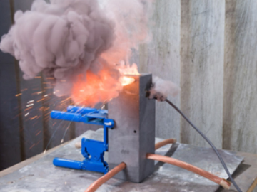
تستر صاعقه گیر وسیله ای است که با استفاده از آن می توان وضعیت مدار داخلی صاعقه گیر الکترونیک خازنی را چک کرده و نیز مدل آن را مشخص نمائیم.
با این دستگاه میتوان از صحت عملکرد صاعقه گیر نصب شده اطمینان حاصل کرد.
عملکرد آن به این نحو است که با اعمال کمیت معینی از ولتاژ و اندازه گیریهای داخلی و فعال نمودن قسمتهای الکترونیکی صحت عملکرد صاعقه گیر مشخص میشود.
تجهیزات تست صاعقه گیر
Permanent link to this article: http://peg-co.com/home/%d8%aa%d8%ac%d9%87%db%8c%d8%b2%d8%a7%d8%aa-%d8%aa%d8%b3%d8%aa-%d8%b5%d8%a7%d8%b9%d9%82%d9%87-%da%af%db%8c%d8%b1/

nowadays, technical installations in all industries are characterized by ever-increasing complexity and automation. From highly developed production lines to robot technology, the amount of equipment that requires a reliable power supply to function smoothly is steadily growing. Therefore, the foundations for reliability and availability of an installation are already laid by selecting the right power supply system. Along with personnel and fire protection, fail safety is the key factor when choosing an appropriate power supply. During the planning phase of an installation, three system types are available: the TN system, the TT system and the IT system
INTRODUCTION
Protective measure always require the coordination of earth connection, types of conductive conductors and protective equipment in relation to the types of earthing systems. This clause describes the systems and their earth connection according to IEC 60364-1
The standard assesses the following characteristics of the distribution system
-
Types of systems of live conductors
-
Types of system earthing
Resulting from his are the following characteristic values for the type of distribution system
-
Type and number of active conductors of the system
The systems are distinguished in AC and DC systems
The following systems of live conductors are taken into account in the standard
| AC System |
DC System |
| Single-phase 2-wire |
۲-wire |
| Single-phase 3-wire |
۳-wire |
| Two-phase 3-wire |
|
| Two-phase 5-wire |
|
| Three-phase 3-wire |
|
| Three-phase 3-wire |
|
Types of Systems Earthing
The various codes used, are derived from the relationship of the distribution system to earth and the relationship of the exposed conductive parts of the electrical installation to earth. Codes used have the following meaning;
| First letter |
Relationship of distribution system to earth |
| T |
Direct connection of one point to earth; |
| I |
All live parts isolated from earth or one point connected to earth through an impedance |
| Second letter |
Relationship of the exposed-conductive-parts of the installation to earth |
| T |
Direct electrical connection of the exposed-conductive-parts to earthing independently of the earthing of any point of the power system; |
| N |
Direct electrical connection of the exposed-conductive-parts to earthed point of the power system (in AC systems, the earthed point of the power system is normally the natural point or, if a neutral point is no available, a phase conductor). |
| Subsequent letter |
Arrangement of neutral and protective conductors |
| S |
Protective function provided by a conductor separate from the neutral of from the earthed line (or in AC systems, earthed phase) conductor. |
| C |
Neutral and protective functions combined in a single conductor (PEN conductor) |
| PE |
Protective conductor. |
The main distributor systems are;
TN System, TT System, IT System
TN System
TN Distributor systems have one point directly earthed, the exposed-conductive-parts of the installation being connected to that point by protective conductors. There are distinct types of TN Systems in relation to the arrangement of neutral and protective conductors. They are as follows

-
TN-S system: throughout the system, a separate protective conductor is used
-
TN-C-S system: neutral and protective functions are combined in a single conductor in a part of the system
-
TN-C system: neutral and protective functions are combined in a single conductor throughout the system
TT System
The TT distributor system has one point directly earthed, the exposed conductive-parts of the installation being connected to earth electrodes electrically

independent of the earth electrodes of the power system
IT System
The IT distribution system has all live parts isolated from earth or one point connected to earth through an impedance, the exposed-conductive-parts of the electrical installation being earthed
-
Independently, or
-
Collectively, or
-
To the earthing of the system

Result
Earthing systems are generally important to protect basic protection (against direct contact) and fault / fault protection (against indirect contact) against bumps and to minimize the risk of fire that can occur. Because the two important values we need to build protection and equip the circuits with the necessary protection devices depend on these systems. These two important values are the fault current and the touch voltage. Because the protection will change by the size of these values. These values depend entirely on what the earthing system is
Permanent link to this article: http://peg-co.com/home/types-of-earthing-systems/

مقدمه:
قفس فاراده یک ققس یا فضای بستهٔ ساختهشده از فلز یا رسانای الکتریکی دیگر است.
قفس فاراده در برابر نفوذ امواج رادیویی و تابش الکترومغناطیسی مقاوم است.
یعنی این امواج نمیتوانند به داخل محلی که مچهز به قفس فاراده است نفوذ کنند.
در سال ۱۸۷۳ میلادی مایکل فارادی در آزمایشی فردی را در یک قفس رسانای بزرگ قرار داد.
و آن را تا حدی شارژ کرد که بارهای الکتریکی به صورت جرقه از گوشههای آن جریان پیدا کردند.
در هنگام نمایش کارکرد این قفس، معمولاً از سیمپیچ تسلا یا مولد وان دو گراف در کنار آن استفاده میشود.
و نشان میدهند که با وجود جرقههایی که بین قفس و مولد یا سیمپیچ زده میشود، فرد درون قفس هیچ آسیبی نمیبیند.
برای حفظ امنیت افرادی که در خارج از قفس قرار دارند قفس را به زمین متصل میکنند،
ولی این کار برای حفظ امنیت فرد درون قفس ضرورتی ندارد.
قفس فاراده علاوه بر اینکه محافظی در برابر امواج بیرونی است، به امواج درون خود نیز اجازهٔ خروج نمیدهد.
در این حالت الکترونهای سطح رسانا به گونهای روی سطح داخلی آن آرایش مییابند که اثر بارهای الکتریکی درون قفس را خنثی کنند.
با این وجود بر اثر جابجایی بارها سطح خارجی قفس نیز باردار میشود.
برای جمعآوری بارهای الکتریکی سطح بیرونی قفس آن را به زمین متصل میکنند.
یک میدان الکتریکی بیرونی باعث بازآرایی بارهای الکتریکی میشود که در نتیجهٔ آن میدان الکتریکی درون قفس بدون تغییر میماند.
هنگامی که یک جسم باردار درون قفس فارادی قرار داده میشود، باری روی بدنهٔ قفس القا میکند که دارای پلاریتهٔ مخالف اما هماندازهٔ بار درون قفس است.
اندازه گیری بار الکتریکی شارژشده بر روی قفس فاراده:
با اتصال قفس به یک دستگاه اندازهگیری الکتریکی میتوان بار الکتریکی درون آن را اندازه گرفت،
از این رو قفس فارده یکی از راههای اندازهگیری بارهای الکتریکی ساکن است.
البته پیش از انجام این کار باید قفس را به زمین متصل کرد تا بارهای الکتریکی روی آن تخلیه شود.
سپس پیش از قراردادن جسم باردار درون آن، باید آن را از زمین جدا نمود.
در عمل برای جلوگیری از تداخل میدانهای ناشی از بارهای خارجی لازم است قفس اصلی در درون یک قفس فاردهٔ دیگر قرار بگیرد.
در این آزمایش اگر ژرفای قفس اصلی خیلی بیشتر از پهنای آن باشد، بدون نیاز به بستن در قفس میتوان به نتایج نسبتاً دقیقی دست یافت.
از مزیتهای این روش اندازهگیری این است که میتواند بار کل یک جسم رسانا یا نارسانا را اندازه بگیرد.
محدودیت آن نیز این است که قفس باید بتواند کل جسم مورد آزمایش را در بر بگیرد.
Permanent link to this article: http://peg-co.com/home/%d8%b3%db%8c%d8%b3%d8%aa%d9%85-%d9%82%d9%81%d8%b3-%d9%81%d8%a7%d8%b1%d8%a7%d8%af%d9%87-%d8%b3%d8%a7%d8%ae%d8%aa%d9%85%d8%a7%d9%86/


 مديريت وبسايت بهروز عليخانی