Monthly Archive: تیر ۱۳۹۶

عمل شیلدینگ، در کابلها، سیستم های الکترونیکی، ساختمان ها و اتاقک هایی که درون آن ها تجهیزات و وسائل حساس الکترونیکی نصب شده، حائز اهمیت شایان است.
از این طریق میتوان از ایجاد جریان های القایی که موجب اضافه ولتاژهای مخرب میشوند، جلوگیری نمود.
لازم بذکر است صحیح شیلد کردن کابل، خصوصا هنگامیکه کابلها از فضای باز (Zone 0) وارد ساختمان میشوند از اهمیت خاصی برخوردار است.
حتی وقتیکه صاعقه یک کیلومتر دورتر از مکان مورد نظر اصابت کند، میزان ولتاژ شوکی (Surge) که در کابل ها القاء میشود ممکن است آنچنان بالا باشد که به تجهیزات برقی متصل به آنها خسارات جدی وارد کند.
اهمیت شیلدینگ در مورد یک ساختمان نیز قابل توجه است.
وقتی که صاعقه ای مستقیم به یک ساختمان یا محلی در نزدیکی آن برخورد میکند، بروز خسارت حتمی است.
بطور مثال اگر صاعقه ای در ۳۰ متری ساختمانی با لوپی (Loop) به ابعاد ۱۰×۱۰ متر فرود آید، ولتاژی در حد ۸۰,۰۰۰ ولت به لوپ القاء میکند که امکان تولید جرقه و تخلیه جریان، محرز است.
خطوط برقی که بطور مناسب شیلد شده اند، به همراه اجرای یک سیستم هم پتانسیل و یکپارچه، میتواند بخوبی کار طراحی بکارگیری تجهیزات تکمیلی حفاظتی را ساده کند.
در این صورت کار حفاظت تجهیزات الکترونیکی هم ارزان و هم ریشه ای، عملی می گردد.
صاعقه گیر اکتیو آذرخش(ساخت ایران)
اجرای این دستورالعمل ها که تقریباً و بطور مقایسه ای مخارجی نزدیک صفر دارد، با در نظر گرفتن اینکه میتوان از:
ستون ها،
آرماتورها،
اسکلت های فلزی،
سقف های کاذب،
آرماتورهای کف،
و بطور کلی آهن آلات خود ساختمان استفاده کرد، کار را بطور محسوسی ارزان و ساده میکند.
به شرطی که کلیه قطعات نامبرده با اجرای یک اتصال الکتریکی، هم پتانسیل شده و اتصال هیچ نقطه ای و قطعه ای فراموش نشود.
و در نهایت این شبکه یکدست و بهم پیوسته از چندین نقطه، به زمین وصل گردد .
قدم های بعدی شیلد کردن، کمی پیچیده تر و سخت تر میشود اما به هر صورت امکان پذیر است.
اتاق های مجزا میتوانند به کمک تورهای فلزی شیلد شوند و کابل هایی را که حتی دارای شیلد نباشند، میتوان با عبور دادن از درون لوله های فلزی یا داکت های فلزی محافظت کرد.
طراحی دقیق شیلدینگ را باید به متخصصین امر سپرد.
صاعقه گیر اکتیو آذرخش(ساخت ایران)
اجرای شیلدینگ میتواند حتی، حفاظت تجهیزات در مقابل شوک های (Surge) ناشی از عملیات سوئیچینگ و یا تخلیه های الکترواستاتیک را نیز بهبود بخشد.
Permanent link to this article: http://peg-co.com/home/%d8%b4%db%8c%d9%84%d8%af%db%8c%d9%86%da%af-%da%86%db%8c%d8%b3%d8%aa/

با مطالعه خاموشی های مختلف(blackout) در نقاط مختلف جهان مشخص می شود که بیشترین عامل دراین خاموشی ها فروپاشی ولتاژ- (voltage collapse) و اضافه باری های پی درپی(cascade overloads) می باشد.
که به سبب تریپ های پی درپی رله ها و مدارشکن ها به وجود می آید.
به همین دلیل استفاده از ادو ات کنترلی و پایدارساز در سیستم قدرت می تواند تا حد زیادی باعث بهبودی پایداری شبکه شود.
وبا بهینه شدن تعادل بین تولید و تقاضای توان از اضافه باری خطوط، و فروپاشی ولتاژ ممانعت به عمل آید.
تعاریف پایداری:
پایداری سیستم قدرت طبق تعریف عبارت است توانایی سیستم قدرت در باقی ماندن در حالت تعادل در شرایط عملکردی عادی سیستم و به دست آوردن نقطه کار متعادل جدید پس از حادث شدن اغتشاش در آن.
در حالت کلی در ادبیات سیستم قدرت با چهار نوع پایداری استاتیکی، دینامیکی، گذرا و ولتاژ مواجه هستیم:
پایداری استاتیکی:
پایداری استاتیکی اشاره دارد به پایداری سیستم قدرت در اثر ایجاد تغییرات کوچک و پیوسته در بار وشرایط اولیه شبکه و باقی ماندن پایداری سیستم با وجود سیستم های تحریک و گاورنر های مرسوم.
برای بهبود پایداری استاتیکی می توان اقدامات زیر را انجام داد:
۱٫افزایش سطح ولتاژ شبکه.
۲٫افزودن خطوط جدید به سیستم انتقال.
۳٫کاهش راکتانس سری خط با باندل کردن خطوط و نصب خازن های سری در خطوط انتقال و کاهش راکتانس سری ترانسفورماتورها (البته کاهش راکتانس سری ترانس ها نباید زیاد باشد تا سطح اتصال کوتاه بالا نرود).
پایداری دینامیکی:
پایداری دینامیکی اشاره دارد به پایداری سیستم قدرت در برابر اغتشاشات ناگهانی ولی کوچک به طوریکه سیستم با معادلات دیفرانسیلی خطی توصیف می شود.
وسیستم می تواند به کمک کنترلرهای پایدارساز شبکه(pss) پایداری خود را حفظ کند.
مثال های نوعی عبارتند از نوسانات فرکانس پایین شبکه ناشی از به هم پیوستن سیستم قدرت پیوسته، و یا نوسانات پیچشی نیروگاه های حرارتی به خاطر رزونانس زیر سنکرون ناشی از نصب خازن های سری جبرانساز در خطوط انتقال.
پایداری گذرا :
پایداری گذرا اشاره دارد به پایداری سیستم قدرت در برابر حادث شدن یک اغتشاش ناگهانی بزرگ که ماورای توانایی یک کنترلر خطی و پیوسته پایدارساز شبکه(pss) برای حفظ پایداری شبکه می باشد.
و ممکن است سیستم پایداری خود را در همان نوسانات اول از دست بدهد.
مگر آنکه از ادوات کنترلی ویا روش های بهبود دهنده پایداری زیر استفاده شود:
-۱ افزایش پایداری استاتیکی که اشاره شد.
-۲ رفع سریع خطای شبکه با به کارگیری سیستم های حفاظتی و دژنکتورهای سریع.
-۳ به کارگیری رله های وصل مجدد.
-۴ به کارگیری کلیدها و دژنکتورهای تک قطبی که فقط فاز معیوب را قطع کنند. (pole single
-۵ استفاده از ماشین ها و ژنراتورهایی با اینرسی بالا و راکتانس کم
-۶ سیستم های تحریک با پاسخ سریع و ضریب بهره بالا از نوع تریستوری.
-۷ (fast valving) شیرزنی سریع در نیروگاه ها
-۸ به کار گیری ترمزهای مقاومتی در نیروگاه ها .(resistor braking
-۹ به کار گیری ادوات facts جهت انعطاف پذیرکردن باس شبکه. Y شبکه با تغییرات بر روی
-۱۰ استفاده از نیروگاه های تلمبه ذخیره ای دور متغیر(dfim)که با تغییر دور و سرعت روتور می توان توان های اکتیو و راکتیو را سریعا کنترل نمود.
-۱۱ نصب خطوط انتقال جریان مستقیم ولتاژبالا(HVDC) ، به موازات خطوط انتقال ac زیرا این خطوط به خاطر دارا بودن مدارهای الکترونیک قدرت کنترل پذیر، قابلیت انتقال توان مورد نیاز تا حد حرارتی خود را دارند.
پایداری ولتاژ :
پایداری ولتاژ اشاره دارد به توانایی سیستم قدرت در نگهداری ولتاز تمامی باس ها در محدوده ی قابل قبول، که این توانایی باید در شرایط عملکرد عادی سیستم و پس از بهبود پایداری در سیستم های قدرت جهت جلوگیری از blackout با استفاده از Pss و ادوات facts حادث شدن اغتشاش باشد.
سیستم زمانی دچار ناپایداری ولتاژ می شود که تقاضای بار به طور ناگهانی افزایش یابد ویا اینکه شرایطی در سیستم به وجود آید که ولتاژ باس ها به طور تصاعدی و غیر قابل کنترلی شروع به افت کنند.
یکی از عواملی مهمی که در ناپایداری ولتاژ نقش بسزایی ایفا می کند، ناتوانی سیستم در تامین توان راکتیو مورد نیاز است.
ناپایداری ولتاژ سبب فروپاشی ولتاژ(voltage collapse) می شود، به طوریکه آنقدر ولتاژ افت می کند که سیستم دیگر قادر به بازیابی آن نیست.
کنترلر های سیستم قدرت :
همانطور که در بخش قبلی اشاره شد راه های زیادی برای بهبود پایداری سیستم قدرت وجود دارد.
در این مقاله اثر کنترلرهای اتوماتیک سیستم قدرت برای حل مشکل دینامیکی و ولتاژ شبکه، بعد از به وجود آمدن اغتشاش مورد مطالعه وبررسی قرار گرفته است.
این کنترلرها factsو Pss عبارتند از:
پایدارساز سیستم قدرت(PSS) پایدارساز سیستم قدرت یک کنترلر سنتی، اقتصادی و موثر در راستای بالا بردن پایداری دینامیکی سیستم قدرت است .
این تجهیز به عنوان یک کنترلر مکمل بر روی سیتم تحریک ژنراتورها نصب می شود .
کار Pss ایجاد میراکنندگی در نوسانات فرکانس پایین ژنراتور است Pss با ایجاد گشتاورهای الکتریکی میراکننده و سنکرون کننده، سبب بهبود انحرافات گردش روتور می شود.
در واقع Pss با ایجاد ولتاژ مثبت یا منفی در مواقع مورد نیاز ولتاژ تحریک را تنظیم و بهینه می کند.
کنترلرهای Facts
ادوات الکترونیک قدرتی هستند که facts کنترلرهای بارپذیری خطوط یا حد پایداری ولتاژ در برابر فروپاشی را افزایش می دهند.
به طور کلی کنترلرهای facts برای کنترل دینامیک ولتاژ، امپدانس و زاویه ی فاز خطوط ac مورد استفاده قرار می گیرد.
کنترلرهای facts می توانند به صورت سری، موازی، و ترکیب سری-موازی در سیستم قرار بگیرند .
کنترلرهای رایج نوع موازی، جبران سازهای استاتیکی توان راکتیو(svc) و جبران سازهای استاتیکی(Statcom) می باشند.
نوع رایج کنترلرهای سری، خازن های سری کنترل شده با ولتاژ(tcsc) و نوع رایج ترکیبی سری -موازی آن کنترلرهای یکپارچه سیلان توان(upfc) می باشد.
با توجه به ساختار شبکه انتخابی برای تامین توان راکتیو و افزایش حد بارپذیری شبکه کنترلر svc برای بهبود دینامیک ولتاژ شبکه و جلوگیری از فروپاشی ولتاژ، انتخاب شده است.
با قابلیت Svc پاسخ سریع و دقیق می تواند با تزریق و یا جذب توان راکتیو ولتاژ شبکه را به خوبی کنترل کند.
Permanent link to this article: http://peg-co.com/home/%d9%be%d8%a7%db%8c%d8%af%d8%a7%d8%b1%db%8c-%d8%af%d8%b1-%d8%b3%db%8c%d8%b3%d8%aa%d9%85-%d9%82%d8%af%d8%b1%d8%aa/
سیستم ارت در جایگاههای تخلیه و بارگیری سوخت
مقاومت سیستم ارت در جایگاههای تخلیه و بارگیری سوخت و مواد نفتی چقدر باید باشد؟
۱- براساس استانداردهای بین المللی , مقدار خاصی برای سیستم زمین ملاک نیست ولی گستردگی ان و توزیع درست و صحیح ان بهمراه رعایت اصول هم پتانسیل سازی در تمامی سطوح پیشنهاد می گردد.
اما اگر شما هیچ یک از موارد مذکور را رعایت ننمودید و سیستم زمین شما به یک الکترود زمین عمقی خلاصه می گردد, توصیه می گردد مطابق IEEE برای پست برق زیر ۵ اهم و مطابق bs حدود ۳ تا ۴ اهم و از نظر سیستم صاعقه گیر IEC زیر ۱۰ اهم باشد.
هرچند ایین نامه های داخلی اعدادی زیر ۱ یا ۲ اهم گفته اند ولی بازم توصیه به همبندی اضافی میشود.
۲- استاندارد API 545 تا حدودی شما را کمک خواهد نمود.
آیا استاندارد خاصی در این زمینه وجود دارد؟
در استاندارد NFPA77 ده اهم است زیرا تخلیه الکترواستاتیک مهم است.
همچنین بیشتر سطح خود تانکری که مایعات دران هست مهم است که انتی استاتیک باشد.
ولی از نظر الکترود زمین توصیه زیر ده اهم است.
مایع کاهنده ارت با نام تجاری ers
نصب سیستم صاعقه گیر نیز در جایگاه های سوخت الزامی است.
با توجه به وسعت جایگاه های سوخت بهترین گزینه استفاده از صاعقه گیر های الکترونیکی است.
صاعقه گیر های الکترونیکی از شعاع پوشش وسیعی برخوردارند.
Permanent link to this article: http://peg-co.com/home/%d8%b3%db%8c%d8%b3%d8%aa%d9%85-%d8%a7%d8%b1%d8%aa-%d8%af%d8%b1-%d8%ac%d8%a7%db%8c%da%af%d8%a7%d9%87%d9%87%d8%a7%db%8c-%d8%aa%d8%ae%d9%84%db%8c%d9%87-%d9%88-%d8%a8%d8%a7%d8%b1%da%af%db%8c%d8%b1%db%8c/

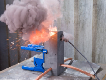
۱- اسپارک گپ از نوع ضد انفجار،جهت بای پس کردن غیرمستقیم عایق فلنچ ها
۲- اسپارک گپ برای حفاظت روشنایی خارجی و سیستم زمین با تحمل جریان صاعقه برای جدایی الکتریکی تجهیزات
۳- اسپارک گپ با درجه حفاظت ip 54، مورد استفاده در سیستم های حفاظتی خارجی، برای پل زدن بین یک نقطه نزدیک سقف استاندارد سیستم ولتاژ پایین و عناصر خارجی سیستم حفاظت صاعقه
۴- اسپارک گپ، مخصوص خطوط لوله نفتی و مواد آتشزا، کوپلینگ سیستم ارتینگ در بخش فناوری اطلاعات، با اتصال موازی، حفاظت موج ولتاژ، برای اتصال سیستم های ارتینگ مختلف.
Permanent link to this article: http://peg-co.com/home/%d8%a7%d9%86%d9%88%d8%a7%d8%b9-%d8%a7%d8%b3%d9%be%d8%a7%d8%b1%da%a9-%da%af%d9%be/
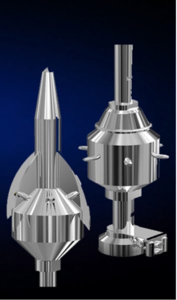
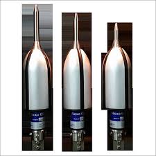
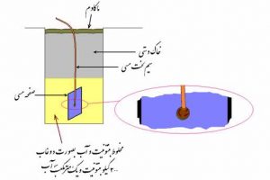
صاعقه گیر های بادی یا پیزو الکتریک
این نوع صاعقه گیر از یک محفظه خالی با مسیر ورود و خروج دوکی شکل آیرو دینامیک ساخته شده است.
ورود و خروج هوا از آن طی یک سیکل و مسیر مشخص صورت می پذیرد و سبب ارتعاش یک الکترود عمودی می شود.
الکترود موصوف به یک سلول پیزوالکتریک متصل است.
نوسانات الکترود سبب ایجاد الکتریسته ساکن در سلول می شود و این انرژی ذخیره شده بین الکترود و جداره خارجی صاعقه گیر تخلیه شده و سبب یونیزاسیون هوای اطراف خواهد شد.
تکنیک فوق، خود کفا اما بسیار حساس و آسیب پذیر است.
چراکه ورود یک جسم خارجی و عدم خروج آن به سبب مسیر دوکی شکل ممکن است باعث انسداد مسیر و از کار افتادن دستگاه شود.
ضمن اینکه وزش هر نوع باد ( که لزوماً صاعقه ای به دنبال ندارد) باعث شارژ شدن بی مورد دستگاه و کاهش طول عمر سلول پیزوالکتریک و عملکرد ارتعاشی آن می شود.
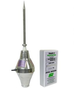
اخیرا جهت رفع نقیصه فوق صاعقه گیرهای نسل جدیدی با نام صاعقه گیر های خازنی الکترونیکی به بازار عرضه شده است.
صاعقه گیر اکتیو خازنی آذرخش(ساخت ایران)
ساختار کلی سیستم صاعقه گیر:
طبق استاندارد یک سیستم حفاظتی صاعقه گیر چه ازنوع پسیو و چه اکتیو شامل سه بخش زیر است:
۱-صاعقه گیر یا ترمینال هوایی (Air Termination)
۲-هادی میانی (Down Conductor)
۳-سیستم زمین یا ترمینال زمین (Earth Termination)
تنها تفاوت اساسی سیستم پسیو و اکتیو در نوع ترمینال هوایی است.
ترمینال هوایی در سیستم پسیو معمولا به شکل میله، سیمهای معلق و یا مش (قفس فارادی) می باشد.
Permanent link to this article: http://peg-co.com/home/%d8%b5%d8%a7%d8%b9%d9%82%d9%87-%da%af%db%8c%d8%b1-%d9%87%d8%a7%db%8c-%d8%a8%d8%a7%d8%af%db%8c-%db%8c%d8%a7-%d9%be%db%8c%d8%b2%d9%88-%d8%a7%d9%84%da%a9%d8%aa%d8%b1%db%8c%da%a9/
مقدمه:
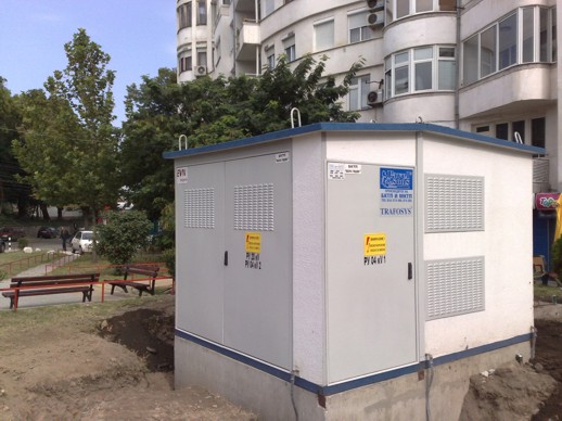
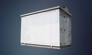
امروزه تراکم بار در مناطق مرکزی محیط های شهری از یک سو، قیمت هنگفت زمین و عدم دسترسی به زمین های با ابعاد مناسب برای ساخت پست های معمولی توزیع از سوی دیگر، موجب شده است تاتقاضا برای انواع پست های کمپکت رو زمینی و زیرزمینی به صورت روزافزون افزایش یابد.
کاهنده مقاومت چاه ارت پست کمپکت

مکمل کاهنده چاه ارت محصولی جدید و فوق العاده موثر در کاهش مقاومت چاه ارت پست کمپکت
((قیمت هر گالن ۵۰۰۰۰ تومان))
این پست ها به طور کلی به دو دسته تقسیم می شوند:
پست های کمپکت پیش ساخته.
مشکلات موجود در انجام عملیات ساختمانی در مراکز پر تراکم، پر ازدحام و پر ترافیک شهری همچون تهران و همچنین لزوم سرعت بخشیدن به عملیات احداث، باعث شده است که استفاده از پست های کمپکت پیش ساخته به عنوان راه حل مناسبی برای پاسخگویی مطرح گردد.
به طور کلی پست های کمپکت پیش ساخته به پست هایی اطلاق می شود که بدون نیاز به عملیات ساختمانی و به صورت آماده شده از قبل و یا با حداقل عملیات ساختمانی (مثلاً فقط با احداث فونداسیون ) قابل نصب در محل باشند.
استفاده از پست های کمپکت پیش ساخته براساس استفاده در شبکه رینگ باز زمینی بوده و بمنظور قرار گرفتن پست در رینگ شبکه، بایستی تابلوی فشارمتوسط به صورت کمپکت دارای دو دستگاه سکسیونر قابل قطع زیر بار و یک دستگاه سکسیونر فوزیبل برای حفاظت ترانس باشد.
با توجه به تراکم بار در مناطق پرازدحام شهری و تجارب موجود، به منظور تنوع زدایی ، ظرفیت این پست ها، ۸۰۰ کیلوولت آمپر در نظر گرفته می شود.
برای طرح های خاص مربوط به مشترکین صنعتی و تجاری با چگالی بار بالا که نیازمند استفاده از پست های اختصاصی با ظرفیت بالاتر از ۸۰۰ کیلوولت آمپر می باشند از رله ثانویه جهت حفاظت ترانسفورماتور استفاده می شود.
دارای روشنایی و تهویه کنترل شده با ترموستات مناسب
نصب پست روی سطح زمین و بر روی فوندانسیون
دارای دریچه ورود به زیر زمین پست از داخل
مجزا بودن قسمت های LV , MV و Transformer از یکدیگر
استفاده از ورق دو و نیم میلیمتر در ساخت بدنه
رنگ الکترواستاتیک / کوره ای
درجه حفاظت IP4X
کاملا پیش ساخته و بصورت پیچ و مهره ای
نصب اسکلت ، قطعات و تجهیزات در مدت زمان کوتاه
حمل و راه اندازی و جابجائی بسیار آسان
بدون نیاز به نگهداری
ابعاد کوچکتر
قابلیت جابجایی در هر زمان
Permanent link to this article: http://peg-co.com/home/%d9%be%d8%b3%d8%aa-%da%a9%d9%85%d9%be%da%a9%d8%aa-%da%86%db%8c%d8%b3%d8%aa-%d9%88-%d9%88%db%8c%da%98%da%af%db%8c-%d9%87%d8%a7%db%8c-%d8%a2%d9%86-%da%a9%d8%af%d8%a7%d9%85%d9%86%d8%af/

سیستم های خورشیدی به سیستم هایی معروفند که تعمیر و نگهداری در آن ها بسیار پایین است و این موضوع با در نظر گرفتن چند نکته بسیار به واقعیت نزدیک است
۱- از آنجایی که پنل های خورشیدی نیاز به تابش مستقیم نور خورشید برای تولید الکتریسیته دارند می بایست در سمت و زاویه ای قرار گیرند که میزان تابش نور خورشید حداکثر باشد.
۲- علاوه بر مورد ۱ می بایست شرایطی را نیز محیا کرد تا این نور حداکثری به پنل برسد.
به این معنی که از کاشت درخت ،قرار دادن هر جسم و شی که باعث جلوگیری رسیدن نور خورشید و ایجاد سابه روی پنل گردد جدا خود داری نمود.
۳- در مناطقی که آلودگی خصوصا از نوع ذرات ریز معلق زیاد است قرار گرفتن این ذرات روی پنل ها باعث کاهش بازدهی شده و عملکرد مناسب این پنل ها به این واسطه تحت الشعاع قرار می گیرد.
به این منظور می بایست در مناطق خاص پنل ها بر اساس نیاز تمیز و در مراقبت از این موضوع اقدامات لازم صورت گیرد.
( تبیین برنامه ریزی معین بر حسب شرایط محیطی جهت نظافت پنل ها ).
۴- با وجود آنکه بر روی تمامی پنل ها صفحه ای پلاستیکی وشفاف با نام لمیننت وجود دارد که از سلول های خورشیدی پنل در مقابل برخورد ضربه مراقبت می نماید اما می بایست از برخورد اشیا سنگین و همچنین ضربه به پنل ها جدا جلوگیری به عمل آید.
چرا که در صورت بروز این مسئله علاوه بر تخریب خود پنل این مشکل در عملکرد سایر پنل ها تاثیر منفی خواهد داشت
ذکر این نکته ضروری است که در صورت رعایت موارد استفاده از پنل های خورشیدی این بخش از سیستم های خورشیدی عمری تا ۲۵ سال نیز خواهد داشت.
و عموم شرکت های تولید کننده این پنل ها در صورت استفاده صحیح این پنل ها را تا ۲۰ سال گارانتی می نمایند
۵- بخش دیگری از سیستم های خورشیدی که در معرض خرابی واقع است باتری است.
باتری ها عموما به علت فعل و انفعالات شیمیای درونی که دارند از عمری محدود برخوردارند و متناسب با سیکل شارژ و دشارژی مشخص عمر می نمایند.
باتری های مورد استفاده در سیستم های خورشیدی می بایست از نوع deep cycle بوده که در آن ها سیکل شارژ و دشارژ به صورت عمیق صورت می گیرد.
مزیت این باتری ها نسبت به سایر باتری ها عمر بالا و ضریب اطمینان بالای عدم خرابی است.
ولی ذکر این نکته در خصوص باتری ها الزامی است که عمر مفید این تجهیز عموما حداکثر ۵ سال بوده و پس از بروز نشانه های خرابی این تجهیز می بایست آن را با باتری نو تعویض نمود.
۶ – نکته آخری که در خصوص عملکرد باتری ها مهم می باشد شرایط کاری باتری است.
همانگونه که در بخش های دیگر نیز گفته شد شرایط نگهداری و کار باتری بسیار در عملکرد و عمر باتری تاثیرگذار بوده و قرار داشتنن این تجهیز در مکانی که از تاثیرات جوی بدور و همچنین دارای شرایط استاندارد آمده در دستورالعمل همراه باتری را داشته باشد بسیار مهم است.
۷-در خصوص شارژ کنترل وهمچنین اینورتر عمدتا مسئله خاصی وجود نداشته و این تجهیزات تا زمانی که در شرایط تعریف شده توسط شرکت سازنده مورد بهره برداری قرار گیرند دچار مشکل و مسئله ای خاص نخواهند گردید.
Permanent link to this article: http://peg-co.com/home/%d8%aa%d8%b9%d9%85%db%8c%d8%b1-%d9%88-%d9%86%da%af%d9%87%d8%af%d8%a7%d8%b1%db%8c-%d8%b3%db%8c%d8%b3%d8%aa%d9%85-%d8%a8%d8%b1%d9%82-%d8%ae%d9%88%d8%b1%d8%b4%db%8c%d8%af%db%8c/
موارد کاربرد سیستم برقگیر الکترونیکی (ESE):
این سیستم بر اساس استاندارد NFC 17-102 برای محافظت ساختمان های عادی با ارتفاع کمتر از ۶۰ متر و فضاهای باز در موارد زیرممکن است مورد استفاده قرارگیرد :
مجموعه های مسکونی ، ساختمان های مختلف مجموعه فرهنگی و آموزشی و مانند آن ، کارخانه های مختلف و پالایشگاه ها وفضاهای باز شامل انبارها و محوطه های تفریحی و رفاهی و …
محدوده حفاظتی هر برقگیر الکترونیک:
این محدوده از گردش شعاع های حفاظتی( (R pn حاصل از ارتفاع های مختلف (hh)حول محور آن به وجود می آید.
شعاع حفاظتی هر برقگیر الکترونیک:
شعاع حفاظت هر برقگیر الکترونیک (Rp) بستگی به ارتفاع نوک آن نسبت به سطح مورد حفاظت (h) پیشروی زمان تخلیـه (ΔT) انتخـاب کلاس حفاظت ( که براسـاس استانداردNFC 17-102 قابل ارزیابی است) مورد نیاز دارد.
که به شرح ذیل محاسبه و تعیین می شود :
Rp : شعاع حفاظت برقگیر
h : ارتفاع نوک میله برقگیر از سطح مورد حفاظت
D : قطر کره فرضی با توجه به کلاس حفاظت یا فاصله برخورد صاعقه
ΔL : فاصله ای که برقگیر نقطه دریافت صاعقه را برابر نظریه گوی فرضی(Fictitious sphere )از نوک پایانه هوایی دور می کند.
کلاس حفاظت(D ) : کلاس حفاظت ، که طبقه بندی سیستم حفاظتی برقگیر الکترونیک در برابر صاعقه است و سطح کارایی آن را بیان می کند ( که شعاع کره یونیزه شده علمدار حمله از طرف ابر می باشد ).
در این استاندارد به سه طبقه به شرح زیر تقسیم شده است :
کلاس۱ : ۲۰ متر = D ، حداکثر حفاظت
کلاس۲ : ۴۵ متر = D ، حفاظت متوسط
کلاس۳ : ۶۰ متر = D ، حفاظت استاندارد
تعریف فاصله ΔL : طول مسافتی که علمدار حمله زمینی در زمان ΔT ، طی میکند ، ΔL نامیده می شود.
این فاصله براساس فرمول :
L(m) = V(m/µs). ΔT(µs)Δ محاسبه می شود .
ΔT زمانی است که برقگیر الکترونیکی زودتر از یک میله ساده ( در ارتفاع مساوی ) صاعقه را دریافت می کند.
و بر اساس یک سری از آزمایشات در آزمایشگاه ها تعیین میگردد ( به این زمان، زمان پیشروی تخلیه نیز گفته میشود) .
V سرعت یونیزاسیون کانال صاعقه می باشد که معادل m/µs1 در نظر گرفته می شود .
صاعقه گیرهای یونیزه کننده هوا:
طراحی و نصب این صاعقه گیر های براساس استاندارد NFC 17-102 انجام می گیرد.
ریشه این استاندارد نیز همان تئوری گوی غلطان است که در تمامی استاندارد ها از آن استفاده شده است.
NFC 17-102 با وارد کردن پارامتر ΔLدر فرمول محاسبات، شعاع پوشش افزایش یافته صاعقه گیر را محاسبه می کند.
صاعقه گیر پس از نصب روی ساختمان، می بایست بوسیله هادیهای میانی Down Conductor از طریق سیم مسی بدون روکش به سیستم زمین متصل گردد.
مقاومت الکترود زمین صاعقه گیر می بایست زیر ۱۰ اهم باشد و پس از اجرا به شبکه هم بتانسیل کل سایت متصل شود.
در اجرای الکترود زمین هر صاعقه گیر می بایست از اقلامی چون صفحه های مسی، مواد کاهنده مقاومت (LOM) ، اتصالات جوش انفجاری استفاده نمود.
((Rp = √( h(2D-h) + ΔL (2D+ ΔL برای H≥۵ meter
H = ارتفاع واقعی نصب صاعقه گیر نسبت به سطح مورد نظر
Rp = شعاع حفاظتی
ΔL = فاصله ای که یون ها در جهت صاعقه می پیمایند (پارامتر متغیر بر حسب نوع و مشخصات صاعقه گیر)
D = درجه پیشرفت صاعقه یا مدت جهش صاعقه در طول مسیر ، که بر اساس درجه حفاظتی تعیین می شود :
Protection Level I : D = 20m
Protection Level II : D = 30m
Protection Level III : D = 45m
Protection Level IV : D = 60m
برای ارتفاع کمتر از ۵ متر ، شعاع حفاظتی از جداول مربوط به هر صاعقه گیر محاسبه می شود.
صاعقه گیر اکتیو آذرخش(ساخت ایران)
Permanent link to this article: http://peg-co.com/home/%d8%b5%d8%a7%d8%b9%d9%82%d9%87-%da%af%db%8c%d8%b1-%d8%af%d8%b1%da%a9%d9%84%d8%a7%d8%b3-%d9%87%d8%a7%db%8c-%d8%ad%d9%81%d8%a7%d8%b8%d8%aa%db%8c-%d9%85%d8%ae%d8%aa%d9%84%d9%81-level-1-3/
برای ایجاد یک ارتباط الکتریکی بین اجزاء و دستگاه ها با زمین جهت هدایت جریان های مختلف به زمین، نیاز به طراحی و اجرای یک سیستم زمین می باشد.
سیستم های زمین مختلف می تواند با اهداف خاصی اجرا گردد.
یکی از مهمترین این اهداف انتقال جریان های خطا به زمین ، به منظور ایجاد ایمنی برای افراد در تاسیسات مختلف می باشد.
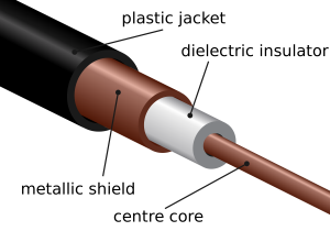
در سیستمهای مخابراتی و الکترونیکی وجود یک سیستم مرجع سیگنال متصل به زمین به منظور هدایت بارهای الکتریکی القایی بر روی بدنه های فلزی لازم و ضروری است.
وظیفه انتقال جریان ها و بارهای الکتریکی به زمین ، برعهده الکترود زمین می باشد.
از طرفی زمین دارای یک فضای هادی با یک مقاومت ویژه است ، بنابراین از دیدگاه نظریه الکترواستاتیک هر الکترود دفن شده در زمین نسبت به نقطه مرجع در بینهایت دارای یک مقاومت الکتریکی است.
طراحی و نحوه قرار گیری اجزاء الکترود در میزان مقاومت بدست آمده تاثیر بسزایی دارد.
مقاومت الکترود زمین وترکیب اجزاء آن همچنین در مقادیر پتانسیلهای سطحی زمین که در اثر جریان خطا بوجود می آیند، متاثر است.
از اینرو لازم است قبل از اجراء سیستم زمین تحقیات گسترده ای در زمینه خاک و عوامل موثر در آن و ویژگیهای بدن انسان انجام گیرد.
در این اینجا یک سری مطالب کلی از سیستم ارتینگ و از جدید ترین منابع علمی اخذ گردیده که با توجه به سادگی متن ورعایت اصول امانت داری در بیان کل مطالب و مفاهیم بدون ترجمه بوده و به راحتی قابل فهم میباشند.
صاعقه گیر اکتیو آذرخش۶۰ با شعاع پوشش وسیع
Earthing and Types of Electrical Earthing – Electrical Grounding Installation (Step by Step)
Earthing, Grounding, Methods Of Earthing, Types of Earthing And Is Specifications In Respect To Earthing Of Electrical Installations
We have to updated this post with different and useful articles related to Earthing & Grounding.
Please Subscribe to Electrical Technology Blog by Email and don’t miss even a single post about the story. OR just see the last paragraph of the article. Thanks
Happy learning
What is Grounding or Earthing?
To connect the metallic (conductive) Parts of an Electric appliance or installations to the earth (ground) is called Earthing or Grounding.
In other words, to connect the metallic parts of electric machinery and devices to the earth plate or earth electrode (which is buried in the moisture earth) through a thick conductor wire (which has very low resistance) for safety purpose is known as Earthing or grounding.
To earth or earthing rather, means to connect the part of electrical apparatus such as metallic covering of metals, earth terminal of socket cables, stay wires that do not carry current to the earth. Earthing can be said as the connection of the neutral point of a power supply system to the earth so as to avoid or minimize danger during discharge of electrical energy.
Good to know
Difference between Earthing, Grounding and Bonding.
Let me clear the confusion among earhing, grounding and bonding.
Earthing and Grounding is the same terms used for earthing. Grounding is the commonly word used for earthing in the North American standards like IEEE, NEC, ANSI and UL etc while, Earthing is used in European, Common wealth countries and Britain standards like IS and IEC etc.
The word Bonding used for jointing two wires (as well as conductors, pipes or appliances together. Bonding is known as connecting the metallic parts of different machines which is not considered to be carrying electric current during normal operation of the machines to bring them at the same level of electric potential.
Need of Earthing or Grounding. Why Earthing is Important?
The primary purpose of earthing is to avoid or minimize the danger of electrocution, fire due to earth leakage of current through undesired path and to ensure that the potential of a current carrying conductor does not rise with respect to the earth than its designed insulation.
When the metallic part of electrical appliances (parts that can conduct or allow passage of electric current) comes in contact with a live wire, maybe due to failure of installations or failure in cable insulation, the metal become charged and static charge accumulates on it. If a person touches such a charged metal, the result is a severe shock.
To avoid such instances, the power supply systems and parts of appliances have to be earthed so as to transfer the charge directly to the earth.
Below are the basic needs of Earthing.
-
To protect human lives as well as provide safety to electrical devices and appliances from leakage current.
-
To keep voltage as constant in the healthy phase (If fault occurs on any one phase).
-
To Protect Electric system and buildings form lighting.
-
To serve as a return conductor in electric traction system and communication.
-
To avoid the risk of fire in electrical installation systems.
Different Terms used in Electrical Earthing
-
Earth: The proper connection between electrical installation systems via conductor to the buried plate in the earth is known as Earth.
-
Earthed: When an electrical device, appliance or wiring system connected to the earth through earth electrode, it is known as earthed device or simple “Earthed”.
-
Solidly Earthed: When an electric device, appliance or electrical installation is connected to the earth electrode without a fuse, circuit breaker or resistance/Impedance, It is called “solidly earthed”.
-
Earth Electrode: When a conductor (or conductive plate) buried in the earth for electrical earthing system. It is known to be Earth Electrode. Earth electrodes are in different shapes like, conductive plate, conductive rod, metal water pipe or any other conductor with low resistance.
-
Earthing Lead: The conductor wire or conductive strip connected between Earth electrode and Electrical installation system and devices in called Earthing lead.
-
Earth Continuity Conductor: The conductor wire, which is connected among different electrical devices and appliances like, distribution board, different plugs and appliances etc. in other words, the wire between earthing lead and electrical device or appliance is called earth continuity conductor. It may be in the shape of metal pipe (fully or partial), or cable metallic sheath or flexible wire.
-
Sub Main Earthing Conductor: A wire connected between switch board and distribution board i.e. that conductor is related to sub main circuits.
-
Earth Resistance: This is the total resistance between earth electrode and earth in Ω (Ohms). Earth resistance is the algebraic sum of the resistances of earth continuity conductor, earthing lead, earth electrode and earth.
POINTS TO BE EARTHED
Earthing is not done anyhow. According to IE rules and IEE (Institute of Electrical Engineers) regulations,
-
Earth pin of 3-pin lighting plug sockets and 4-pin power plug should be efficiently and permanently earthed.
-
All metal casing or metallic coverings containing or protecting any electric supply line or apparatus such as GI pipes and conduits enclosing VIR or PVC cables, iron clad switches, iron clad distribution fuse boards etc should be earthed (connected to earth).
-
The frame of every generator, stationary motors and metallic parts of all transformers used for controlling energy should be earthed by two separate and yet distinct connections with the earth.
-
In a dc 3-wire system, the middle conductors should be earthed at the generating station.
-
Stay wires that are for overhead lines should be connected to earth by connecting at least one strand to the earth wires.
Components of Earthing System
A complete electrical earthing system consists on the following basic components.
-
Earth Continuity Conductor
-
Earthing Lead
-
Earth Electrode
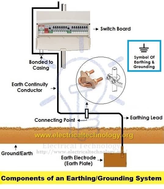
Components of Electrical Earthing System
Earth Continuity Conductor or Earth Wire
That part of the earthing system which interconnects the overall metallic parts of electrical installation e.g. conduit, ducts, boxes, metallic shells of the switches, distribution boards, Switches, fuses, Regulating and controlling devices, metallic parts of electrical machines such as, motors, generators, transformers and the metallic framework where electrical devices and components are installed is known as earth wire or earth continuity conductor as shown in the above fig.
The resistance of the earth continuity conductor is very low. According to IEEE rules, resistance between consumer earth terminal and earth Continuity conductor (at the end) should not be increased than 1Ω. In simple words, resistance of earth wire should be less than 1Ω.
Size of the Earth Continuity Conductor or Earth Wire depends on the cable size used in the wiring circuit.
Size of Earth Continuity Conductor
The cross sectional area of the Earth Continuity Conductor should not be less than the half of the cross sectional area of the thickest wire used in the electrical wiring installation.
Generally, the size of the bare copper wire used as earth continuity conductor is 3SWG. But keep in mind that, don’t use less than 14SWG as earth wire. Copper strip is also can be used as earth continuity conductor instead of bare copper wire but don’t go for it until manufacture recommend it.
Earthing Lead or Earthing Joint
The conductor wire connected between earth continuity conductor and earth electrode or earth plate is called earthing joint or “Earthing lead”. The point where earth continuity conductor and earth electrode meet is known as “connecting point” as shown in the above fig.
Earthing lead is the final part of the earthing system which is connected to the earth electrode (which is underground) through earth connecting point.
There should be minimum joints in earthing lead as well as lower in size and straight in the direction.
Generally, copper wire can be used as earthing lead but, copper strip is also used for high installation and it can handle the high fault current because of wider area than the copper wire.
A hard drawn bare copper wire is also used as an earthing lead. In this method, all earth conductors connected to a common (one or more) connecting points and then, earthing lead is used to connect earth electrode (earth plat) to the connecting point.
To increase the safety factor of installation, two copper wires are used as earthing lead to connect the device metallic body to the earth electrode or earth plate. I.e. if we use two earth electrodes or earth plats, there would be four earthing leads. It should not be considered that the two earth leads are used as parallel paths to flow the fault currents but both paths should work properly to carry the fault current because it is important for better safety.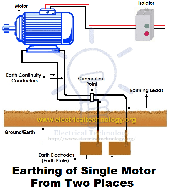
Size of the Earthing Lead
The size or area of earthing lead should not be less than the half of the thickest wire used in the installation.
The largest size for earthing lead is 3SWG and the minimum size should not be less than 8SWG. If 37/.083 wire is used or the load current is 200A from the supply voltage, then it is recommended to use copper strip instead of double earthing lead. The earth lead connection methods is shown in the above fig.
Note: We will post additional article about Earth Plate size with simple calculations… Stay tune.
Earthing Electrode or Earth Plate
A metallic electrode or plate which is buried in the earth (underground) and it is the last part of the electrical earthing system. In simple words, the final underground metallic (plate) part of the earthing system which is connected with earthing lead is called earth plate or earth electrode.
A metallic plate, pipe or rode can be used as an earth electrode which has very low resistance and carry the fault current safely towards ground (earth).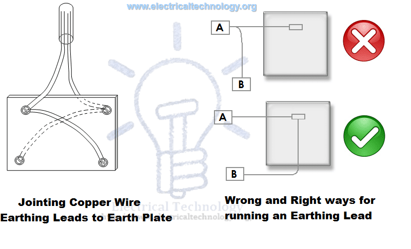 Size of Earthing Electrode
Both copper and iron can be used as earthing electrode.
The size of earth electrode (In case of copper)
۲×۲ (two foot wide as well as in length) and 1/8 inch thickness.. I.e. 2’ x 2’ x 1/8”. (۶۰۰x600x300 mm)
In case of Iron
۲’ x2’ x ¼” = ۶۰۰x600x6 mm
It is recommended to bury the earth electrode in the moisture earth. If it is not possible, then put water in the GI (Galvanized Iron) pipe to make possible the moisture condition.
In the earthing system, put the earth electrode in vertical position (underground) as shown in the above fig. Also, put a 1 foot (about 30cm) layer of powdered charcoal and lime mixture around the earth plate (don’t confuse with earth electrode and earth plate as both are the same thing).
This action makes the possible increase in the size of the earth electrode which leads a better continuity in the earth (earthing system) and also helps to maintain the moisture condition around earth plate.
P.S: We will post Example calculation about Earth Electrode Sizing… Stay tune.
Good to know:Don’t use coke (after burning coal in the furnace to emit all the gases and other components, the remaining 88% carbon is called coke) or stone coal instead of charcoal (wood coal) because it causes to corrosion in the earth plate.
Since, the water level is different in the different areas; therefore, the depth for earth electrode installation is also different in various areas. But, the depth for earth electrode installation should not be less than 10ft (3 meter) and should below 1 foot (304.8mm) from the constant water level.
Motors, Generator, Transformers etc should be connected from to earth electrode two different places.
Earth Plate or Earth Electrode Size for Small installation
In small installation, use metallic rod (diameter = 25mm (1inch) and length = 2m (6ft) instead of earth plate for earthing system. The metallic pipe should be 2 meter below from the surface of ground. To maintain the moister condition, put 25mm (1inch) coal and lime mixture around the earth plate.
For effectiveness and convenience, you may use the copper rods 12.5mm (0.5 inch) to 25mm (1 inch) diameter and 4m (12ft) length. We will discuss the installation method of rod earthing latter.
Methods of Earthing | Types of Earthing
Earthing can be done in many ways. The various methods employed in earthing (in house wiring or factory and other connected electrical equipment and machines) are discussed as follows:
۱). Plate Earthing:
In plate earthing system, a plate made up of either copper with dimensions 60cm x 60cm x 3.18mm (i.e. 2ft x 2ft x 1/8 in) or galvanized iron (GI) of dimensions 60cm x 60cm x 6.35 mm (2ft x 2ft x ¼ in) is buried vertical in the earth (earth pit) which should not be less than 3m (10ft) from the ground level.
For proper earthing system, follow the above mentioned steps in the (Earth Plate introduction) to maintain the moisture condition around the earth electrode or earth plate.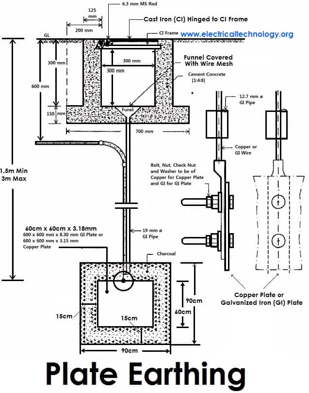
۲). Pipe Earthing:
A galvanized steel and a perforated pipe of approved length and diameter is placed vertically in a wet soil in this kind of system of earthing. It is the most common system of earthing.
The size of pipe to use depends on the magnitude of current and the type of soil. The dimension of the pipe is usually 40mm (1.5in) in diameter and 2.75m (9ft) in length for ordinary soil or greater for dry and rocky soil. The moisture of the soil will determine the length of the pipe to be buried but usually it should be 4.75m (15.5ft).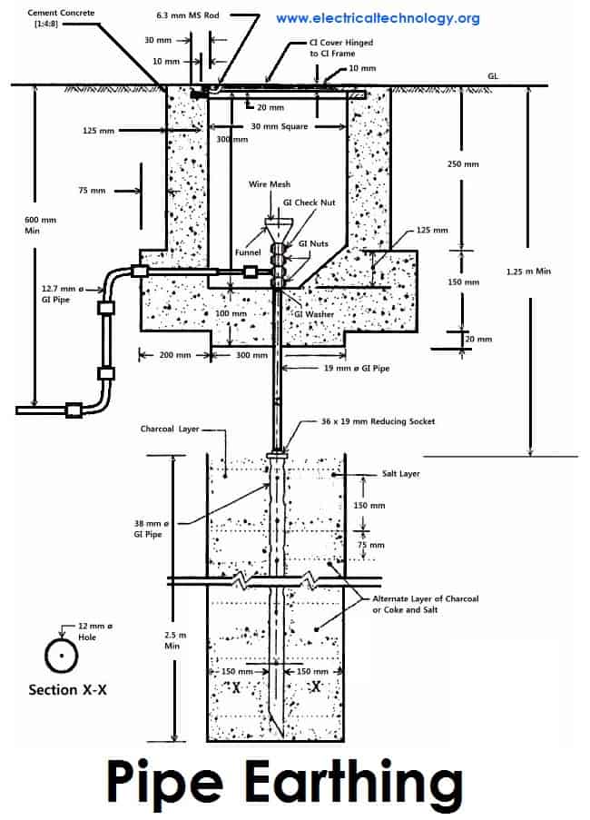
۳). Rod Earthing
it is the same method as pipe earthing. A copper rod of 12.5mm (1/2 inch) diameter or 16mm (0.6in) diameter of galvanized steel or hollow section 25mm (1inch) of GI pipe of length above 2.5m (8.2 ft) are buried upright in the earth manually or with the help of a pneumatic hammer. The length of embedded electrodes in the soil reduces earth resistance to a desired value.
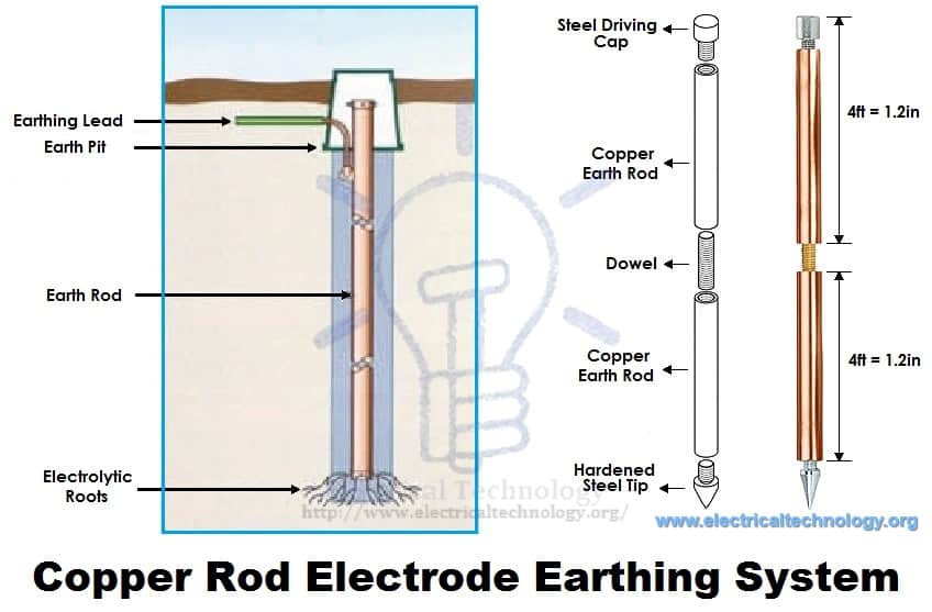 Copper Rod Electrode Earthing System
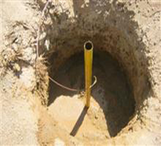
۴). Earthing through the Waterman
In this method of earthing, the waterman (Galvanized GI) pipes are used for earthing purpose. Make sure to check the resistance of GI pipes and use earthing clamps to minimize the resistance for proper earthing connection.
If stranded conductor is used as earth wire, then clean the end of the strands of the wire and make sure it is in the straight and parallel position which is possible then to connect tightly to the waterman pipe.
۵). Strip or Wire Earthing:
In this method of earthing, strip electrodes of cross-section not less than 25mm x 1.6mm (1in x 0.06in) is buried in a horizontal trenches of a minimum depth of 0.5m. If copper with a cross-section of 25mm x 4mm (1in x 0.15in) is used and a dimension of 3.0mm2 if it’s a galvanized iron or steel.
If at all round conductors are used, their cross-section area should not be too small, say less than 6.0mm2 if it’s a galvanized iron or steel. The length of the conductor buried in the ground would give a sufficient earth resistance and this length should not be less than 15m.
General method of Earthing / Proper Grounding Installation (Step by Step)
The usual method of earthing of electric equipments, devices and appliances are as follow:
-
First of all, dig a 5x5ft (1.5×۱٫۵m) pit about 20-30ft (6-9 meters) in the ground. (Note that, depth and width depends on the nature and structure of the ground)
-
Bury an appropriate (usually 2’ x 2’ x 1/8” (۶۰۰x600x300 mm) copper plate in that pit in vertical position.
-
Tight earth lead through nut bolts from two different places on earth plate.
-
Use two earth leads with each earth plate (in case of two earth plates) and tight them.
-
To protect the joints from corrosion, put grease around it.
-
Collect all the wires in a metallic pipe from the earth electrode(s). Make sure the pipe is 1ft (30cm) above the surface of the ground.
-
To maintain the moisture condition around the earth plate, put a 1ft (30cm) layer of powdered charcoal (powdered wood coal) and lime mixture around the earth plate of around the earth plate.
-
Use thimble and nut bolts to connect tightly wires to the bed plates of machines. Each machine should be earthed from two different places. The minimum distance between two earth electrodes should be 10 ft (3m).
-
Earth continuity conductor which is connected to the body and metallic parts of all installation should be tightly connected to earth lead.
-
At last (but not least), test the overall earthing system through earth tester. If everything is going about the planning, then fill the pit with soil. The maximum allowable resistance for earthing is 1Ω. If it is more than 1 ohm, then increase the size (not length) of earth lead and earth continuity conductors. Keep the external ends of the pipes open and put the water time to time to maintain the moisture condition around the earth electrode which is important for the better earthing system.
SI specification for Earthing
Various specifications in respect to earthing as recommended by Indian Standards are given below. Here are few;
-
An earthing electrode should not be situated (installed) close to the building whose installation system is being earthed at least more than 1.5m away.
-
The earth resistance should be low enough to cause the flow of current sufficient to operate the protective relays or blow fuses. It’s value is not constant as it varies with weather because it depends on moisture (but should not be less than 1 Ohm).
-
The earth wire and earth electrode will be the same material.
-
The earthing electrode should always be placed in a vertical position inside the earth or pit so that it may be in contact with all the different earth layers.
Dangers Of Not Earthing A Supply System
As emphasized on earlier, earthing is provided in order
-
To avoid electric shock
-
To avoid risk of fire as a result of earth leakage current through unwanted path and
-
To ensure that no current carrying conductor rises to a potential with respect to general mass of earth than its designed insulation.
However, if excessive current is not earthed, appliances will be damaged without the help of fuse in place. You should note that excessive current are earthed at their generating stations which is why earth wires carries very little or no current at all. It therefore implies that it is not necessary to earth any of the wires (live, earth and neutral wires) contained in a PVC. Earthing the live wire is catastrophic.
I have seen a person killed simply because a live wire got cut from overhead pole and fell to the ground while the ground was wet. Excessive current is earthed at generating stations and if at all the earthing is not efficient due to fault, earth fault interrupters will be there to help. Fuse help only when the power transmitted is above the rating of our appliances, it blocks the current from reaching our appliances by blowing off and protecting our appliances in the process.
In our electrical appliances, if excessive currents are not earthed, we would experience severe shock. Earthing takes place in electrical appliances only when there is a problem and it is to save us from danger. If in an electronic installation, a metallic part of an electrical appliance comes in direct contact with a live wire that results from maybe failure of installation or otherwise, the metal will be charged and static charge will accumulate on it.
If you happen to touch the metallic part at that moment you will be zapped. But if the metallic part of the appliance is earthed, the charge will be transferred to earth instead of accumulating on the metallic part of the appliance. Current don’t flow through earth wires in electrical appliances, it does so only when there is problem and only to direct the unwanted current to earth in order to protect us from severe shock.
In addition, if a live wire touches accidentally (in a faulty system) to the metallic part of a machine. Now, if a man touches that metallic part of the machine, then the current will flow through their body to the ground, hence, he will get shocked (electrocuted) which may lead to serious injuries even to death. That’s why earthing is so important?
Electrical Grounding & Earthing….. To be continued…
Please subscribe below, if you want to get the upcoming post about Earthing/Grounding such as:
-
Calculate the size of Earth Continuity Conductor, Earthing Lead & Earth Electrodes for differnt electrical devices and equipment such motors, transformers, home wiring etc by Simple calculations
-
Earthing Circuit and Earth Fault Current
-
Protection of Earthing System and Additional devices used in the Earthing / Grounding System
-
Points To remember while Providing Grounding / Earthing
-
Important Instruction for Proper earthing system
-
Electricity rules about Earthing
-
How to Test Earth Resistance by Earth Tester
-
How to test Earth loop Resistance by Am-Meter & Voltmeter
-
Protective Multiple Earthing
-
And much more….
Permanent link to this article: http://peg-co.com/home/%d8%b3%db%8c%d8%b3%d8%aa%d9%85-%d8%a7%d8%b1%d8%aa-earthing/

سیستم ارت مناسب بایستی امپدانس الکتریکی بسیار پایین ، مقاومت مکانیکی بسیار بالاو مقاومت بالا در برابر خوردگی داشته باشد.
انواع زمین کردن الکتریکی عبارت است از :
۱-زمین کردن به شکل مستقیم ،
۲-زمین کردن از طریق مقاومت،
۳-زمین کردن از طریق راکتانس،
۴-زمین کردن از طریق ترانسفورماتور و زمین کردن ایزوله می باشد.
صاعقه گیر اکتیو آذرخش
انواع زمین کردن حفاظتی شامل:
گراند تجهیزات،
گراند صاعقه گیر،
گراندبارهای ساکن،
گراند ایزوله،
گراند منفرد یا مستقل
گراند شبکه ای سیگنال مرجع می باشد.
برای اجرای ارت دو روش وجود داردیکی روش عمقی بوده و دیگری روش سطحی می باشد که روش عمقی از چاه برای اجرای ارت استفاده می شود و در روش سطحی،سیستم ارت در سطح زمین اجرا می گردد.
در صورتی می توان از روش سطحی استفاده نمود که فضای لازم به منظور حفاری وجود داشته باشد، ارتفاع از سطح دریا پایین باشد و پستی و بلندی های محوطه کم باشد.
برای تست نمودن سیستم های ارتینگ روش هایی نظیر:
روش افت ولتاژ ،
روش ۶۲درصد،
روش تنزل پتانسیل،
و روش خط عرضی وجود دارد.
که بهترین روش اندازه گیری همان روش افت ولتاژ می باشد.
و عمومی ترین روش اندازه گیری روش خط اصلی است.
الکترودهای اتصال به زمین به دو دسته تقسیم می گردندکه شامل الکترودهای مصنوعی و الکترودهای موجود یا طبیعی می باشند.
الکترودهای صفحه ای شامل ، الکترودهای قائم و الکترودهای افقی می باشند.
چاه ارت
اجرای چاه ارت
تست چاه ارت
قیمت چاه ارت
Permanent link to this article: http://peg-co.com/home/%d8%b3%db%8c%d8%b3%d8%aa%d9%85-%d8%a7%d8%b1%d8%aa-%db%8c%d8%a7-%d8%b2%d9%85%db%8c%d9%86-%da%a9%d8%b1%d8%af%d9%86-%d8%a7%d9%84%da%a9%d8%aa%d8%b1%db%8c%da%a9%db%8c/