Monthly Archive: اردیبهشت ۱۳۹۸

مقدمه:
شیلدینگ امواج الکترومغناطیسی در واقع کاهش شدت میدان الکترومغناطیسی در فضا است.
کاهش اثر امواج الکترو مغناطیسی از طریق مسدود کردن امواج با استفاده از موانع رسانا یا مواد مغناطیسی صورت میگیرد.
شیلدینگ امواج الکترومغناطیسی اغلب در راستای ایزوله سازی سیستم ها و ساختار های خاص و حیاتی صورت میگیرد.
استفاده از سیستم شیلدینگ در مکانهای زیر از اهمیت خاصی برخوردار است:
سایت های نظامی
بیمارستان ها
نیروگاه های برق
مراکز داده(دیتا سنترز)
فرستنده ها و گیرندههای رادیو و تلویزیون
سیستم های مخابراتی
سایت های پتروشیمی و پالایشگاه
What is Passive Magnetic Shielding
Rigid (passive) magnetic shielding is divided into two fundamental types based upon the magnetic and conductive properties of the shielding materials: flux-entrapment shields and lossy shields
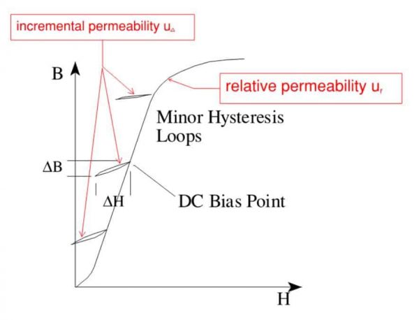
A flux-entrapment or flux ducting shield is constructed with a permeable (μ) ferromagnetic material such as low-carbon steel, silicon-iron steel (oriented and non-oriented) and nickel-iron alloy which either surrounds (cylinder or rectangular box) or separates (“U” shaped or flat-plate) the victim (i.e., people or equipment) from the magnetic field source. Ideally, magnetic flux lines incident upon the flux entrapment shield prefer to enter the permeable (μ) material via the path of least magnetic reluctance ℜ, rather than pass into the protected (shielded) space. The higher the permeability the more magnetic flux lines will prefer to travel within the material rather than a lower permeable material including air (or vacuum) which has the lowest mu (μ) of 1
Lossy shielding depends on the eddy-current losses that occur within highly conductive copper and aluminum materials, and higher permeable (μ) ferromagnetic materials that are also less conductive. When a highly conductive materials are subjected to a time-varying (60Hz) magnetic fields, currents are induced within the material that flow in closed circular paths, perpendicular to the inducing field. According to Lenz’s Law, these eddy-currents oppose changes in the inducing field, therefore the magnetic fields produced by the circulating eddy-currents attempt to cancel the larger external fields near the conductive surface, thereby generating a very effective shielding effect
What’s Your Shielding Factor
Shielding Factor (SF) is the ratio between the unperturbed magnetic field Bo and the shielded magnetic field Bi as expressed in: SF = Bi/Bo The final shielding design depends on several critical factors: maximum predicted worst-case 60-Hz magnetic field intensity (magnitude and polarization) and the geomagnetic (DC static) field at that location- whichever is greater; shield geometry and volumetric area; type of materials, permeability, induction & saturation; and, number of shield layers
Permanent link to this article: http://peg-co.com/home/%d8%b4%db%8c%d9%84%d8%af%db%8c%d9%86%da%afshielding-system/
مقدمه:
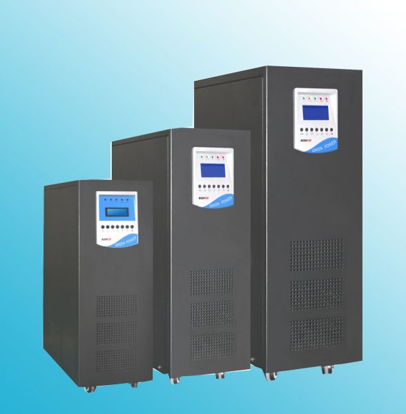
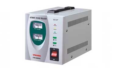
تثبیت کننده ولتاژ یا استابلایزر یک دستگاه الکتریکی است که برای ارائه ولتاژ ثابت به یک بار در پایانه های خروجی آن صرف نظر از تغییرات ورودی یا ولتاژ منبع ورودی طراحی شده است.
این دستگاه در برابر ولتاژ بالا و سایر ولتاژهای دیگر محافظت می کند.
همچنین این دستگاه رگولاتور ولتاژ اتوماتیک (AVR) نامیده می شود.
تثبیت کننده های ولتاژ برای تجهیزات الکتریکی با ارزش و گران قیمت ترجیح داده می شود تا از نوسانات مضر کم و ولتاژ آنها محافظت کند.
برخی از این تجهیزات عبارتند از تهویه مطبوع، دستگاه چاپ افست، تجهیزات آزمایشگاهی، ماشین آلات صنعتی و دستگاه های پزشکی.
تکنولوژی جدید در ساخت استابلایزر:
تعبیه فناوری تراشه ریز پردازنده و دستگاه های الکترونیکی قدرت در طراحی تثبیت کننده های ولتاژ AC (یا تنظیم کننده های ولتاژ اتوماتیک (AVR)) منجر به تولید منبع تغذیه با کیفیت بالا و پایدار در صورت انحراف قابل توجه و مداوم ولتاژ منبع تغذیه می شود.
همزمان با پیشرفته شدن استابلایزرهای ولتاژ معمولی رله، استابلایزر مدرن از مدارهای کنترل دیجیتال با کارایی بالا و مدار کنترل حالت جامد استفاده می کنند که تنظیمات پتانسیومتر را از بین می برد و کاربر را قادر می سازد ولتاژ مورد نیاز را از طریق یک صفحه کلید تنظیم کند.
این همچنین منجر به زمان بندی یا پاسخ استابلایزر به میزان بسیار کمتر، معمولا کمتر از چند میلی ثانیه است، علاوه بر این می توان با واریابل آنرا تنظیم کرد.
امروزه استابلایزرها به یک راه حل بهینه شده برای بسیاری از وسایل الکترونیکی که حساس به نوسانات ولتاژ هستند حساس هستند و کار با دستگاه های بسیاری مانند دستگاه های CNC، تهویه مطبوع، تلویزیون، تجهیزات پزشکی، رایانه ها، تجهیزات مخابراتی و غیره را در بر دارد.
Permanent link to this article: http://peg-co.com/home/%d8%aa%da%a9%d9%86%d9%88%d9%84%d9%88%da%98%db%8c-%d8%ac%d8%af%db%8c%d8%af-%d8%af%d8%b1-%d8%b3%d8%a7%d8%ae%d8%aa-%d8%a7%d8%b3%d8%aa%d8%a7%d8%a8%d9%84%d8%a7%db%8c%d8%b2%d8%b1/
UPS مخفف عبارت Uninterruptible power supply ، به معنای منبع تغذیه بدون وقفه است.
یوپی اس یک منبع تغذیه الکترونیکی است که وظیفه اصلی آن ، تامین بدون وقفه ی توان مورد نیاز بار مصرفی می باشد ، این سیستم بین برق شهر و دستگاه مصرف کننده قرار گرفته علاوه بر تثبیت و تنظیم برق شبکه مانع از نفوذ نویز و اختلالات شبکه به تجهیزات حساس مصرف کننده می گردد . همچنین یوپی اس به عنوان منبع توان بدون وقفه با استفاده از انرژی ذخیره شده در باتری ، برق مورد نیاز تجهیزات مصرف کننده را تامین می نماید .
درحقیقت استفاده از یک انرژی پشتیبان مانند سیستم تامین انرژی بدون وقفه (UPS) شما را قادرمیسازد که بربیشترمشکلات ناشی ازبرق شهرفائق آیید وهمچنین محافظت دربرابرقطع کلی برق را نیز بدست آورید.
شما می توانید سطوح مختلفی ازحفاظت را درمقابل مشکلات برق برای سیستم خود جهت جلوگیری ازتخریب ویا ازدست دادن اطلاعات به کارگیرید.
UPS System
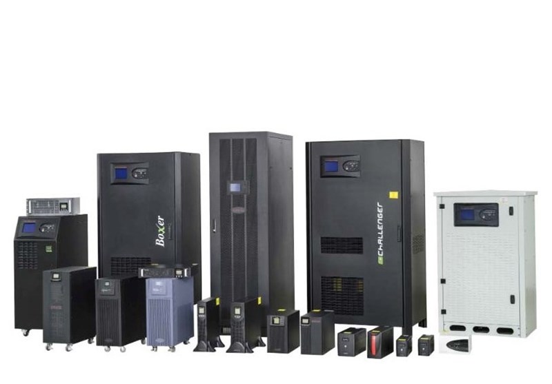
The term UPS is an abbreviation for “Uninterruptible Power Supply”. To guard against peaks and drops in voltage, UPS systems are an indispensable security system with a multitude of specialist applications that meet the sophisticated technological demands of the world we live in today. UPS systems are utilised in any situation where a constant, regular and secure power supply is required
UPS Systems for safe and secure Emergency Power Supply
Hospitals, banks, printing houses, computer and logistic centres, broadcasters, surveillance facilities etc. are dependent on a reliable power supply in case of mains failure. Follow up costs and loss of reputation due to power failures are no longer a threat with a UPS system in place
The constant development of UPS systems with regard to the production of smaller and more compact shapes, the most cutting-edge technology and lowest prices have enabled them to be utilised in every conceivable environment or working situation, for e.g. as industry ups system. With customer specific inventions and adaptations, Wärtsilä JOVYATLAS can supply the optimum UPS solution in all operational sectors and for any application
We would like to support you by choosing the right UPS solution adapted to your concrete and individual needs
UPS systems ensure power to critical targets
UPS (Uninterruptible Power Supply) systems are used in order to ensure an uninterrupted supply of power to critical targets. A UPS system will provide a constant and steady supply of electricity for the devices served by it. If the UPS detects a problem with the main electrical supply, it instantly switches over to its battery backup system, minimising any problems to the end user
UPS systems are used in
-
Data centres
-
Hospitals
-
Power plants
-
Industrial facilities
-
Network nodes, such as base stations
-
Corporate intranets
-
Extensive UPS expertise
We handle data centre projects and installations of UPS systems, batteries and cables with expertise. We collaborate with well-known system suppliers who are able to respond quickly and competently to clients’ urgent maintenance needs
Permanent link to this article: http://peg-co.com/home/ups-system-%d8%b3%db%8c%d8%b3%d8%aa%d9%85-%db%8c%d9%88-%d9%be%db%8c-%d8%a7%d8%b3/
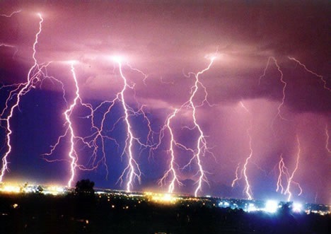
آذَرخش یا رعد و برق گونهای تخلیه الکتریکی است که در اثر الکتریسیته ایستا میان دو ابر یا ابر و زمین ایجاد میشود. هرچند آذرخش اشاره به درخشش الکتریکی ست که میان ابر و زمین است. چه، درخشش الکتریکی میان دو ابر در واقع دِرَخش یا رَخش یا همان برق نام دارد.
در اثر برخورد ذرات آب یک جبهه هوای گرم به ذرات یخ یک جبهه هوای سرد، الکتریسیته ساکن بوجود میآید که نسبت به زمین دارای بار الکتریکی منفی بوده و در صورتی که فاصله منبع جریان الکتریکی کم و بیش، نزدیک به سطح زمین باشد، آذرخش بروز میکند. در آذرخشهای شدید بیشترین برونداد الکتریکی رخ میدهد. دما در محل اصابت برق فوقالعاده بالا میرود (حدود ۲۸٬۰۰۰ درجه کلوین)
基本概念
大气中的水蒸气是雷云形成的内因;雷云的形成也与自然界的地形以及气象条件有关。
.热雷电是夏天经常在午后发生的一种雷电,经常伴有暴雨或冰雹。热雷电形成很快、持续时间不长,۱~۲小时;雷区长度不超过۲۰۰~۳۰۰km,宽度不超过几十千米。热雷电形成必须具备以下条件。
空气非常潮湿,空气中的水蒸气已近饱和,这是形成热雷电的必要因素。
晴朗的夏天、烈日当头,地面受到持久暴晒,靠近地面的潮湿空气的温度迅速提高,人们感到闷热,这是形成热雷电的必要条件。
无风或小风,造成空气湿度和温度不均匀。无风或小风的原因可能是这里气流变化不大,也可能是地形的缘故(如山中盆地)。
上述条件逐渐形成云层,同时云层因极化而形成雷云。出现上述条件的地点多在内陆地带,尤其是山谷、盆地。
.强大的冷气流或暖气流同时侵入某处,冷暖空气接触的锋面或附近可产生冷锋雷电。
冷锋雷(或叫寒潮雷)的形成是强大的冷气流由北向南入侵时,因冷空气较重,所以冷气流就像一个楔子插到原来较暖而潮湿的空气下面,迫使暖空上升,热而潮的空气上升到一定高度,水蒸气达到饱和,逐渐形成雷云。冷锋雷是雷电中最强烈的一种,通常都伴随着暴雨,危害很大。这种雷雨一般沿锋面几百千米长、۲۰~۶۰km宽的带形地区发展,锋面移动速度每小时۵۰~۶۰km,最高可达每小时۱۰۰km。
暖锋雷(或叫热潮雷)的形成是当暖气流移动到冷空气地区,逐渐爬到冷空气上面所引起的。它的发生一般比冷锋雷缓和,很少发生强烈的雷雨
现象简介
“雷电”自然现象
雷电是伴有闪电和雷鸣的一种雄伟壮观而又有点令人生畏的放电现象。雷电一般产生于对流发展旺盛的积雨云中,因此常伴有强烈的阵风和暴雨,有时还伴有冰雹和龙卷风。积雨云顶部一般较高,可达۲۰公里,云的上部常有冰晶。冰晶的凇附,水滴的破碎以及空气对流等过程,使云中产生电荷。云中电荷的分布较复杂,但总体而言,云的上部以正电荷为主,下部以负电荷为主。因此,云的上、下部之间形成一个电位差。当电位差达到一定程度后,就会产生放电,这就是我们常见的闪电现象。闪电的的平均电流是۳万安培,最大电流可达۳۰万安培。闪电的电压很高,约为۱亿至۱۰亿伏特。一个中等强度雷暴的功率可达一千万瓦,相当于一座小型核电站的输出功率。放电过程中,由于闪电通道中温度骤增,使空气体积急剧膨胀,从而产生冲击波,导致强烈的雷鸣。 带有电荷的雷云与地面的突起物接近时,它们之间就发生激烈的放电。在雷电放电地点会出现强烈的闪光和爆炸的轰鸣声。这就是人们见到和听到的闪电雷鸣。
种类
连发式雷电
雷电分直击雷、电磁脉冲、球形雷、云闪四种。其中直击雷和球形雷都会对人和建筑造成危害,而电磁脉冲主要影响电子设备,主要是受感应作用所致;云闪由于是在两块云之间或一块云的两边发生,所以对人类危害最小。
直击雷就是在云体上聚集很多电荷,大量电荷要找到一个通道来泄放,有的时候是一个建筑物,有的时候是一个铁塔,有的时候是空旷地方的一个人,所以这些人或物体都变成电荷泄放的一个通道,就把人或者建筑物给击伤了。直击雷是威力最大的雷电,而球形雷的威力比直击雷小。
雷云的形成
产生雷电的条件是雷雨云中有积累并形成极性。科学家们对雷雨云的带电机制及电荷有规律分布,进行了大量的观测和试验,积累了许多资料,并提出各种各样的解释,有些论点还有争论。
۱对流云初始阶段的“离子流”假说
大气中存在这大量的正离子和负离子,在云中的雨滴上,电荷分布是不均匀的,最外边的分子带负电,里层的带正电,内层比外层的电势差约高۰٫۲۵V。为了平衡这个电势差,水滴就必须优先吸收大气中的负离子,这就使水滴逐渐带上了负电荷。当对流发展开始时,较轻的正离子逐渐的被上升的气流带到云的上部;而带负电的云滴因为比较重,就留在了下部,造成了正负电荷的分离。
自然现象-雷电(۲۰张)
۲冷云的电荷积累
当对流发展到一定阶段,云体伸入۰℃层以上的高度后,云中就有了过冷水滴、霰粒和冰晶等。这种由不同相态的水汽凝结物组成且温度低于۰℃的云,叫冷云。冷云的电荷形成和积累过程有如下几种:
① 过冷水滴在霰粒上撞冻起电
在云层重有许多水滴在温度低于۰℃时也不会冻结,这种水滴叫过冷水滴。过冷水滴是不稳定的,只要它们被轻轻地震动一下,就马上冻结称冰粒。当过冷水滴与霰粒碰撞时,会立即冻结,这叫撞冻。当发生撞冻时,过冷水滴外部立即冻成冰壳,但它的内部仍暂时保持着液态,并且由于外部冻结放的潜热传到内部,其内部液态过冷水的温度比外面的冰壳高。温度的差异使得冻结的过冷水滴外部带上正电,内部带上负电。当内部也发生冻结时,云滴就膨胀分裂,外表皮破裂成许多带正电的冰屑,随气流飞到云层上部,带负电的冻滴核心部分则附在较重的霰粒上,使霰粒带负电并留在云层的中下部。
② 冰晶与霰粒的摩擦碰撞起电
霰粒是由冻结水滴组成的,成白色或乳白色,结构比较松脆。由于经常有冷水滴与它撞冻并释放潜热,它的温度一般比冰晶高。在冰晶中含有一定量的自由离子(OH-和H+),离子数随温度升高而增多。由于霰粒与冰晶接触部分存在着温度差,高温端的自由离子必然要多于低温端,因而离子必然从高温端向低温端迁移。离子迁移时,带正电的氢离子速度较快,而带负电的较重的氢氧根离子则较慢。因此,在一定时间内就出现了冷端氢离子过剩的现象,造成了高温端为负,低温端为正的电极化。当冰晶与霰粒接触后,又分离时,温度较高的霰粒就带上了负电,而温度较低的冰晶就带上了正电。在重力和上升气流的作用下,较轻的带正电的冰晶集中到云的上部,较重的带负电的霰粒则停留在云层的下部,因而造成了冷云的上部带正电而下部带负电。
③ 水滴因含有稀薄盐分而起电
出了上述冷云的两种起电机制外,还有人提出了由于大气中水滴含有稀薄盐分而产生起电机制。当云滴冻结时,冰的晶格中可以容纳负的氯离子,却排斥正的钠离子。因此,水滴冻结的部分带负电,而未冻结的部分带正电(水滴冻结时是从里向外进行的)。由于水滴冻结而成的霰粒在下落的过程中,摔掉表面还未来得及冻结的水分,形成许多带正电的小云滴,而冻结的核心部分则带负电。由于重力和气流的分选作用,电正点的小滴被带到云的上部,而带负电的霰粒则停留在云的中、下部。
暖云的电荷积累
在热带地区,有一些云整个云体都位于۰℃以上区域。因而只含有水滴而没有固态水粒子。这种云叫暖云或水云。暖云也会出现雷电现象。在中纬度地区的雷暴云,云体位于۰℃等温线一下的部分,就是云的暖区。在云的暖区里也有起电过程发生。
在雷雨云的发展过程中,上数机制在不同的发展阶段分别起作用。但是,最主要的带电机制还是由于水滴冻结造成的。大量观测事实表明,只有当云顶呈现纤维状,丝缕结构时,云彩发展成为雷雨云。飞机观测发现,雷雨云中存在以冰、雪晶和霰粒为主的大量云粒子,而且大量电荷的积累即雷雨云迅猛带电机制,必须依靠霰粒生长过程的碰撞、撞冻和摩擦等才能发生。
避雷技术
由中国科学院研究员、国际宇航科学院院士在国际上首次提出了通过消除雷击危险性,使保护目标不再遭受雷击的新一代避雷技术,称为“智能避雷技术” 。以原中国科学院空间中心电学组专家团队,经过十多年的潜心研究开发,从理论分析、模拟计算、实验测试、模型实验、工程实用化研究、外场实验等各个角度和方法的研究,都证明了这一技术的合理性和可行性。期间经多次大小各类专家会议的评审鉴定,得到充分肯定,被誉为“۲۱世纪防雷事业的曙光” 。
.地形雷电一般出现于地形空旷地区,它的规模较小,但比较频繁
Permanent link to this article: http://peg-co.com/home/%d8%a2%d8%b0%d8%b1%d8%ae%d8%b4%e9%97%aa%e7%94%b5%ef%bc%8c%e9%9b%b7%e7%94%b5/
Grounding (Earthing) is a system of electrical circuits that are connected to the ground that functions when a leakage current can discharge electricity to the earth
According to Institute of Electrical and Electronics Engineers (IEEE) Standard 142 ™ ۲۰۰۷, the purpose of the grounding system is to:
Limit the amount of voltage to the earth to be within the allowed limits
Provide a path for current flow that can provide detection of the occurrence of an undesired relationship between the system conductor and the earth. This detection will result in the operation of automatic equipment that decides the supply of voltage from the conductor.
Characteristics of an Effective Grounding System
Based on the IEEE standards, the grounding system is divided into:
TN-S (Terre Neutral – Separate)
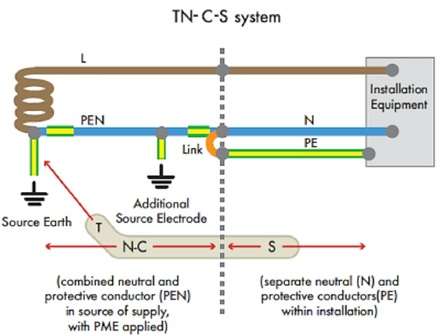
TN-C-S (Terre Neutral – Combined – Separate)
TT (Double Terre)
TN-C (Neutral Terre – Combined)
IT (Isolated Terre)
Terre originates from the French language and means earth.
The first letter is the connection between ground and the power supply, while the second letter shows the connection between ground and electronic equipment supplied with electricity. The meaning of each letter is as follows:
T (Terra) = Direct connection to ground.
I (Isolation) = There is no connection to ground (even if there is a high impedance)
N (Neutral) = Connection directly to neutral power supply cable (where this cable is also grounded in the power supply)
TN-S (Terre Neutral – Separate)

In a TN-S system, the neutral part of the electrical energy source is connected to the earth at one point, so that the neutral part of a consumer installation is directly connected to the neutral source of electricity. This type is suitable for installations that are close to electrical energy sources, such as for large consumers who have one or more HV / LV transformers for their own needs and if the installation / equipment is adjacent to the energy source (transformers)
TN-C-S (Terre Neutral – Combined – Separate)

A TN-C-S system, has a neutral channel from the main distribution equipment (power source) connected to the earth and earthing at a certain distance along neutral channels leading to consumers, usually referred to as Protective Multiple Earthing (PME). With this system, a neutral conductor can function to restore the earth fault current that might arise on the consumer’s side (instation) back to the power source. In this system, the installation of equipment in the consumer only connects the ground to the terminal (channel) provided by the power source
TT (Double Terre)

In the TT system, the neutral part of the electricity source is not directly connected with neutral earthing on the consumer side (equipment installation). In TT systems, consumers must provide their own connection to the earth, namely by installing an earth electrode that is suitable for the installation
TN-C (Neutral Terre – Combined)
In the TN-C system, the neutral channel of the main distribution equipment (power source) is connected directly to the consumer’s neutral channel and the frame of the installed equipment.
With this system, a neutral conductor is used as a protective conductor and a combination of neutral and earthing side frames of the equipment is known as a conductor of PEN (Protective Earthing and Neutral).

This system is not permitted for conductors less than 10 mm2 or for portable equipment. This is because if a fault occurs, then at the same time the PEN conductor carries the phase unbalance current and the third level harmonic current and its multiples.
To reduce the impact on equipment and living things around the equipment, then in the application of the TN-C system, the PEN conductor must be connected to a number of electrode rods for earthing on the installation
IT (Isolated Terre)
From the first letter (I) it is clear that, in this type of IT system, neutral is isolated (not connected) to the earth. The PE point is not connected to the neutral channel but directly connected to the earthing.

In its application, the neutral point of the IT system is not really isolated from the earth, but is still linked to the Zs impdedance which has a very high value of around 1000 ohms to 3000 ohms. This serves the purpose of limiting the level of voltage overload when there is interference in the system.

Permanent link to this article: http://peg-co.com/home/grounding-system/
مقدمه:
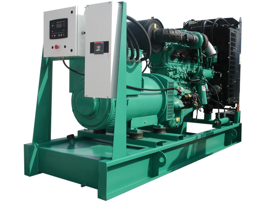
دیزل ژنراتورهای چینی این روزها مانند دیگر محصولات چینی شمار مشخص و رو به افزایشی را در بازار به خود اختصاص داده اند و البته قسمت قابل توجهی از نیاز جامعه صنعتی کشور را نیز بر طرف کرده اند.
در این مقاله چند نوع از دیزل ژنراتورهای چینی که از مرغوبیت نسبتا بالاتری نسبت به سایر برندهای چینی موجود در بازار ایران برخوردار هستند معرفی شده است.
۱-ژنراتور استامفورد چین STAMFORD POWER
ژنراتور استامفورد پاور ساخته کشور چین تحت لیسانس اسنامفورد انگلیس میباشد.
این ژنراتور در دو مدل تک بلبرینگ و شافت دار موجود میباشد.و از لحاظ کیفیت بسیار مرغوب میباشد و قیمت مناسبی هم دارد.
۲-دیزل ژنراتور لوول LOVOL:
LOVOL یک شرکت تولید دیزل ژنراتور به روش مدرنیزه است که براساس سرمایه گذاری مشترک موتورهای پرکینز چین و بریتانیا تاسیس شد.
این دیزل ژنراتورها دارای مزیت های چون مصرف سوخت پایین، تراکم بالا از قدرت، ظاهر و عملکرد خوب نسب به قیمت آن است.
۳-دیزل ژنراتور کامینز چین (Cummins-China)
دیزل ژنراتور کامینز چینی به طور معمول با ژنراتور هایی چون Stamford Power و StamFord بر روی شاسی و بصورت کامینز چینی کوپله فابریک و کامینز چینی کوپله داخل همراه با تابلو دستی ( Manuall ) و امرجنسی و به شکل شاسی باز یا اتاقک سایلنت ( Canopy ) تحویل مشتریان می گردد.
۴-موتور برق جیانگ دونگ JIANG DONG
موتور برق های جیانگ دونگ نیز یکی از بهترین برندهای موتور برق ساخت چین در ایران می باشد.
۵-موتور برق لانسین LONCIN
موتور برق های لانسین چین از بهترین برندهای موتور برق در ایران می باشد که ازقیمت بسیار مناسبی برخوردار است.
Permanent link to this article: http://peg-co.com/home/%d8%af%db%8c%d8%b2%d9%84-%da%98%d9%86%d8%b1%d8%a7%d8%aa%d9%88%d8%b1%d9%87%d8%a7%db%8c-%d9%85%d8%b1%d8%ba%d9%88%d8%a8-%da%86%db%8c%d9%86%db%8c/

مقدمه:
سیستمهای حفاظتی با توجه به نوع صاعقه گیر به دو نوع پسیو (غیر فعال) و اکتیو (فعال) تقسیم می شوند.
سیستم پسیو نسبت به عملکرد صاعقه هیچ گونه واکنشی نداشته و از اینرو پسیو، غیر فعال یا ساده نامیده می شود.
در حالی که صاعقه گیر اکتیو یا(Early Streamer Emission) مجهز به سیستمی است که دارای زمان فعال سازی (Triggering Advance Δt) میباشد.
صاعقه گیر اکتیو هنگام صاعقه ، نسبت به جذب صاعقه عملکرد سریعتری دارد.
زمان فعال سازی نسبت به یک صاعقه گیر ساده در شرایط یکسان سنجیده می شود.
سیستم پسیو در واقع همان چیزی است که فرانکلین ابداع کرده بود.
وجود (Δt) موجب افزایش شعاع حفاظتی در صاعقه گیر اکتیو می شود که عملکرد این نوع را در مقایسه با سیستم پسیو بر جسته می نماید.
سایر اجزاء سیستم مانند هادی میانی و ترمینال زمین در هر دو سیستم مشابه است.
همانگونه که توضیح داده شد صاعقه گیر فعال یا اکتیو که با عبارت ESE نیز شناخته میشوند با ایجاد کانال بالارونده به صورت مصنوعی، موجب عملکرد سریعتر و افزایش شعاع حفاظتی میشود.
اصول عملکرد:
در هوای ابری و پر طلاطم، میدان الکتریکی در فضا تولید میگردد.
که مقدار آن از ۱۰kv/meter شروع و با گذر زمان بیشتر و بیشتر میشود.
وقتی شدت میدان الکتریکی به حد ۵۰kv/meter برسد، زمان شکست عایقی بین ابر و زمین یا مابین دو ابر باردار فرا رسیده است.حاصل این تخلیه وقوع صاعقه میباشد.
بلوک الکتریکی این تجهیز (Energy Block) از طریق شاخکهای بیرونی و میله میانی متصل به زمین شارژ میشود.
و انرژی موجود در هوا را چنانچه توضیح داده شد، بطور مداوم جذب و روی هم انباشته میکند.
و اندک زمانی قبل از وقوع صاعقه، بلوک الکتریکی موصوف انرژی انباشته شده را بوسیله سه شاخک تخلیه میکند.
بدین ترتیب رودخانهای از یونهای آزاد شده بطرف ابر جهت میگیرند.
و با زبانههایی که از طرف ابر به طرف زمین کشیده شده برخورد کرده و مسیری ترجیحی برای تخلیه صاعقه از طریق این برقگیر ایجاد مینماید.
هر صاعقه گیر فعال (E.S.E) با مقدار ΔT شناخته میشود.
این فاکتور مهمترین عامل در کارکرد یک صاعقه گیر یونیزه کننده هوا است.
ΔT زمانی است که این صاعقه گیر زودتر از یک میله ساده (در آزمایشگاه فشار قوی) صاعقه را به زمین تخلیه میکند و واحد آن میکرو ثانیه است.
بر اساس استاندارد NFC ۱۷-۱۰۲ یک سری تست در آزمایشگاه فشار قوی برای محاسبه زمان تخلیه در مقایسه با یک میله ساده برای هر صاعقه گیر یونیزه کننده انجام میگیرد.
از نتایج حاصل از این آزمایشها مقدار ΔT محاسبه میگردد.
Permanent link to this article: http://peg-co.com/home/%d8%b9%d9%85%d9%84%da%a9%d8%b1%d8%af-%d8%b5%d8%a7%d8%b9%d9%82%d9%87-%da%af%db%8c%d8%b1-ese/

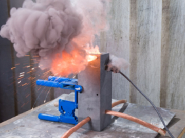
تجهیزات تست صاعقه گیر:
هرسیستم حفاظت درمقابل صاعقه میبایستی به صورت دوره ای و منظم مورد بازبینی و تست قرار بگیرد.
در این خصوص میپتوان به استانداردهای تدوین شده مراجعه نمود.
بعنوان مثال:
صفحه ۷۲ استاندارد BS6651،
ویاصفحه ۲۹استاندارد NFP 780 ،
و همچنین صفحه ۳۷ و ۳۸ استاندارد NFC17-102.
تست اجزاء اصلی سیستم صاعقه گیر و رعایت دستورالعملها و توصیه های استاندارد در خصوص نگهداری و بازبینی آن به بهره برداری صحیح و اصولی از صاعقه گیر نصب شده یاری می رساند.
تستر صاعقه گیر وسیله ای است که با استفاده از آن می توان وضعیت مدار داخلی صاعقه گیر الکترونیک خازنی را چک کرده و نیز مدل آن را مشخص نمائیم.
با این دستگاه میتوان از صحت عملکرد صاعقه گیر نصب شده اطمینان حاصل کرد.
عملکرد آن به این نحو است که با اعمال کمیت معینی از ولتاژ و اندازه گیریهای داخلی و فعال نمودن قسمتهای الکترونیکی صحت عملکرد صاعقه گیر مشخص میشود.
تجهیزات تست صاعقه گیر
Permanent link to this article: http://peg-co.com/home/%d8%aa%d8%ac%d9%87%db%8c%d8%b2%d8%a7%d8%aa-%d8%aa%d8%b3%d8%aa-%d8%b5%d8%a7%d8%b9%d9%82%d9%87-%da%af%db%8c%d8%b1/

nowadays, technical installations in all industries are characterized by ever-increasing complexity and automation. From highly developed production lines to robot technology, the amount of equipment that requires a reliable power supply to function smoothly is steadily growing. Therefore, the foundations for reliability and availability of an installation are already laid by selecting the right power supply system. Along with personnel and fire protection, fail safety is the key factor when choosing an appropriate power supply. During the planning phase of an installation, three system types are available: the TN system, the TT system and the IT system
INTRODUCTION
Protective measure always require the coordination of earth connection, types of conductive conductors and protective equipment in relation to the types of earthing systems. This clause describes the systems and their earth connection according to IEC 60364-1
The standard assesses the following characteristics of the distribution system
-
Types of systems of live conductors
-
Types of system earthing
Resulting from his are the following characteristic values for the type of distribution system
-
Type and number of active conductors of the system
The systems are distinguished in AC and DC systems
The following systems of live conductors are taken into account in the standard
| AC System |
DC System |
| Single-phase 2-wire |
۲-wire |
| Single-phase 3-wire |
۳-wire |
| Two-phase 3-wire |
|
| Two-phase 5-wire |
|
| Three-phase 3-wire |
|
| Three-phase 3-wire |
|
Types of Systems Earthing
The various codes used, are derived from the relationship of the distribution system to earth and the relationship of the exposed conductive parts of the electrical installation to earth. Codes used have the following meaning;
| First letter |
Relationship of distribution system to earth |
| T |
Direct connection of one point to earth; |
| I |
All live parts isolated from earth or one point connected to earth through an impedance |
| Second letter |
Relationship of the exposed-conductive-parts of the installation to earth |
| T |
Direct electrical connection of the exposed-conductive-parts to earthing independently of the earthing of any point of the power system; |
| N |
Direct electrical connection of the exposed-conductive-parts to earthed point of the power system (in AC systems, the earthed point of the power system is normally the natural point or, if a neutral point is no available, a phase conductor). |
| Subsequent letter |
Arrangement of neutral and protective conductors |
| S |
Protective function provided by a conductor separate from the neutral of from the earthed line (or in AC systems, earthed phase) conductor. |
| C |
Neutral and protective functions combined in a single conductor (PEN conductor) |
| PE |
Protective conductor. |
The main distributor systems are;
TN System, TT System, IT System
TN System
TN Distributor systems have one point directly earthed, the exposed-conductive-parts of the installation being connected to that point by protective conductors. There are distinct types of TN Systems in relation to the arrangement of neutral and protective conductors. They are as follows

-
TN-S system: throughout the system, a separate protective conductor is used
-
TN-C-S system: neutral and protective functions are combined in a single conductor in a part of the system
-
TN-C system: neutral and protective functions are combined in a single conductor throughout the system
TT System
The TT distributor system has one point directly earthed, the exposed conductive-parts of the installation being connected to earth electrodes electrically

independent of the earth electrodes of the power system
IT System
The IT distribution system has all live parts isolated from earth or one point connected to earth through an impedance, the exposed-conductive-parts of the electrical installation being earthed
-
Independently, or
-
Collectively, or
-
To the earthing of the system

Result
Earthing systems are generally important to protect basic protection (against direct contact) and fault / fault protection (against indirect contact) against bumps and to minimize the risk of fire that can occur. Because the two important values we need to build protection and equip the circuits with the necessary protection devices depend on these systems. These two important values are the fault current and the touch voltage. Because the protection will change by the size of these values. These values depend entirely on what the earthing system is
Permanent link to this article: http://peg-co.com/home/types-of-earthing-systems/

مقدمه:
قفس فاراده یک ققس یا فضای بستهٔ ساختهشده از فلز یا رسانای الکتریکی دیگر است.
قفس فاراده در برابر نفوذ امواج رادیویی و تابش الکترومغناطیسی مقاوم است.
یعنی این امواج نمیتوانند به داخل محلی که مچهز به قفس فاراده است نفوذ کنند.
در سال ۱۸۷۳ میلادی مایکل فارادی در آزمایشی فردی را در یک قفس رسانای بزرگ قرار داد.
و آن را تا حدی شارژ کرد که بارهای الکتریکی به صورت جرقه از گوشههای آن جریان پیدا کردند.
در هنگام نمایش کارکرد این قفس، معمولاً از سیمپیچ تسلا یا مولد وان دو گراف در کنار آن استفاده میشود.
و نشان میدهند که با وجود جرقههایی که بین قفس و مولد یا سیمپیچ زده میشود، فرد درون قفس هیچ آسیبی نمیبیند.
برای حفظ امنیت افرادی که در خارج از قفس قرار دارند قفس را به زمین متصل میکنند،
ولی این کار برای حفظ امنیت فرد درون قفس ضرورتی ندارد.
قفس فاراده علاوه بر اینکه محافظی در برابر امواج بیرونی است، به امواج درون خود نیز اجازهٔ خروج نمیدهد.
در این حالت الکترونهای سطح رسانا به گونهای روی سطح داخلی آن آرایش مییابند که اثر بارهای الکتریکی درون قفس را خنثی کنند.
با این وجود بر اثر جابجایی بارها سطح خارجی قفس نیز باردار میشود.
برای جمعآوری بارهای الکتریکی سطح بیرونی قفس آن را به زمین متصل میکنند.
یک میدان الکتریکی بیرونی باعث بازآرایی بارهای الکتریکی میشود که در نتیجهٔ آن میدان الکتریکی درون قفس بدون تغییر میماند.
هنگامی که یک جسم باردار درون قفس فارادی قرار داده میشود، باری روی بدنهٔ قفس القا میکند که دارای پلاریتهٔ مخالف اما هماندازهٔ بار درون قفس است.
اندازه گیری بار الکتریکی شارژشده بر روی قفس فاراده:
با اتصال قفس به یک دستگاه اندازهگیری الکتریکی میتوان بار الکتریکی درون آن را اندازه گرفت،
از این رو قفس فارده یکی از راههای اندازهگیری بارهای الکتریکی ساکن است.
البته پیش از انجام این کار باید قفس را به زمین متصل کرد تا بارهای الکتریکی روی آن تخلیه شود.
سپس پیش از قراردادن جسم باردار درون آن، باید آن را از زمین جدا نمود.
در عمل برای جلوگیری از تداخل میدانهای ناشی از بارهای خارجی لازم است قفس اصلی در درون یک قفس فاردهٔ دیگر قرار بگیرد.
در این آزمایش اگر ژرفای قفس اصلی خیلی بیشتر از پهنای آن باشد، بدون نیاز به بستن در قفس میتوان به نتایج نسبتاً دقیقی دست یافت.
از مزیتهای این روش اندازهگیری این است که میتواند بار کل یک جسم رسانا یا نارسانا را اندازه بگیرد.
محدودیت آن نیز این است که قفس باید بتواند کل جسم مورد آزمایش را در بر بگیرد.
Permanent link to this article: http://peg-co.com/home/%d8%b3%db%8c%d8%b3%d8%aa%d9%85-%d9%82%d9%81%d8%b3-%d9%81%d8%a7%d8%b1%d8%a7%d8%af%d9%87-%d8%b3%d8%a7%d8%ae%d8%aa%d9%85%d8%a7%d9%86/