Print this نوشته
صاعقه گیر LPI
:Lightning_Protection_LPI_Stormaster
Direct Strike Lightning Protection for Solar PV Plants LPS Installer TESTED NF C 17-102 (2011) STANDARD
Direct Strike Lightning Protection for Solar PV Plants The LPI story Lightning Protection International Pty Ltd (LPI) is a fully Australian owned manufacturer and supplier of direct strike lightni uppression, and earthing / grounding solutions. For many years, LPI have been providing specialist lightning protection advice to customers in some of the most lightning prone areas of the world. Our personnel have extensive experience in risk management, system design, training, installation, certification, and commissioning of systems in a wide variety of industry groups. LPI’s range of products and services are exported from its head office and research facility (in Tasmania, Australia) and via regional offices worldwide. The company has been recognised within Australia for its outstanding export successes and has been awarded several prestigious export awards. LPI’ s 4-Step Approach to Lightning Protection It is the strategic aim of our company to be able to provide a complete packaged solution. LPI has identified 4 key steps when considering the complete approach to lightning protection, ask for our LPI 4 Step approach to lightning protection. Our system design approach includes: Definition and provision of area protection Creation of a bonded earthing system Protection of mains power lines Protection of signal, data and communication lines
LIGHTNING & SURGE PROTECTION FOR SOLAR PV PLANT For such a complex type of installation as a solar power plant, it is necessary to make an assessment of the damage risk due to lightning strikes according to IEC 62305-2 (EN 62305-2), the result to be taken into account on designing. In case of a solar powerplanttheaimistoprotectboththebuildingandthePVarray against damage by fire (direct lightning strike) and the electrical & electronic systems (inverters, remote diagnostics system, generator) against the effects of lightning electromagnetic impulses (LEMP) Most of the solar module manufacturers offer a warranty of 20 years or more on their products. The cost of such devices is then calculated on this very long period. However those installations are very regularly exposed to lightnings and overvoltages, which can considerably reduce the desired life expectancy. The use of adapted surge protections is then highly recommended. Several aspects have to be considered to evaluate the risk of “Lightning and Overvoltages” : The more the solar panel field is expanded, the more the risk of “lightning” issue is important. The risk is multiple: direct effect (lightning impact directly on the modules) and indirect effect (overvoltages on modules, on the converter/inverter and other connections). When the Photovoltaic devices are located on industrial sites, the risk of operation overvoltages should be taken into account as well. The risks level is directly linked to the density of local lightning and the exposure of the lines. With the growing awareness of global warming and the need for effective energy conservation, we are increasingly looking to new sources of renewable and eco-friendly energy. One of the front-runners in this search for ‘safe’ power is the use of photovoltaic (PV) and/or solar thermal sources – in other words, Solar Power. Such systems by design are located outdoors, and as such are susceptible to the damaging effects of lightning strike. Surge currents and surge voltages constitute a severe threat for PV systems. To ensure safe and reliable operation, these systems must be protected with suitable direct lightning protection system, earthing and surge protection device. Solar Photovoltaic (PV) plants are always wide spread and isolated extentions or roof top installations. The cost of the equipment is high and their damage is detrimental to power supply, especially if they are connected to the distribution network. Their working is controlled by sensitive electronic equipment that may be severely affected by transient over voltages. Therefore, they are high risk installations for lightning protection. Solar Farms – such systems by design are located outdoors and as such are susceptible to the damaging effects of lightning strike Direct Strike Lightning Protection for Solar PV Plants
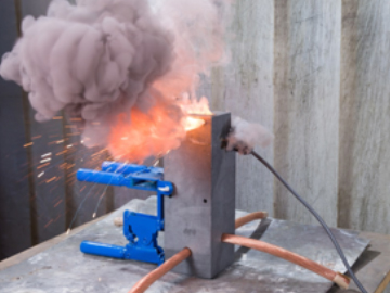
The phenomena of lightning Negatively charged stepped leader moves towards ground Launch of upstreamer from highest ground point as field intensification rises During the formation of a cumulonimbus (cloud forming a towering mass with a flat base at fairly low altitude and often a flat top, as in thunderstorms), there is an increase of ionisation and a potential difference is generated between the thunder cloud and the ground, which gives rise to small discharges. As the electric field gains in strength, the descending leader breaks up the dielectric field in the air. Ultimately, this may break through the layers of dielectric field in the air and strike the surface via the upward propagating tracer from the surface. In normal conditions there is a balance between positive and negative charges in the atmosphere, where the ground is more negatively charged than the air and the elements placed on the ground. However, the formation of storm clouds creates a charge polarization; usually, the lower part of the cloud is charged negatively, inducing then a positive charge at the ground and other elements on it. The electric field at the atmosphere can reach kilovolts in a short span of time. When the electric field is high enough, the cloud starts discharging towards the ground. The path formed by this discharge is called “downward leader” and produces a very sharp variation of the electric field, causing the corona effect. One of these objects/structure will be forming the upward leader, which will move towards the downward leader thus forming the discharge path between the cloud and the ground. This object/structure will be hit with the lightning strike. The cloud charge will try to find the straightest/shortest path to earth and if this path is not controlled, damages can be severe. Electrical effects: Damages/ destruction to the electrical & electronic equipments. Abnormal rise in ground voltage and surges/ transients can damage all the equipment connected to the electrical network. Electrodynamical effects: Structure/building damages. The conductors & equipments which falls within the vicinity of the flow of lightning current are submitted to mechanical strengths due to the magnetic field originated. This may cause deformations and rupture the conductors & equipments. Thermal effects: Lightning strikes can lead to fires. Heat dissipation by the Joule effect can even cause fires. Effects on living beings: Electrocutions and burns. Currents passing through during a short lapse are enough for electrocution risk by respiratory or cardiac arrest. Further burn risk appears. Induction effects: Within a variable electromagnetic field, induced currents appear in every conductor. The consequences of all these effects are important economical losses because of the damages in buildings and equipment due to lightning strike. Lightning can cause service interruptions, stops production processes or force to switch off and on again the utility machinery if the control equipment is affected by lightning. FIGURE 1 Stepped leader progresses towards ground Upstreamer is attracted towards stepped leader FIGURE 2 Leader and streamer meet to form ionised path for lightning discharge FIGURE 3 Direct Strike Lightning Protection for Solar PV Plants
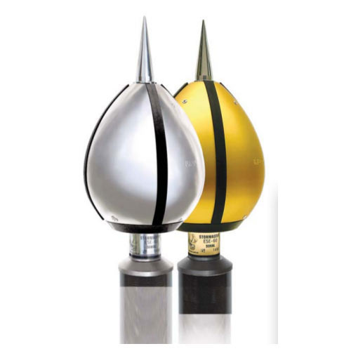
LPI’s Stormaster ESE The LPI Stormaster (Early Streamer Emission) range of terminals provides a safe and efficient system for the protection of your facility from direct lightning strikes. The LPI Stormaster ESE terminal captures the lightning energy at a preferred point. How does the LPI Stormaster ESE Terminal work? The Stormaster ESE air terminal uses the naturally occurring electrical field to complete the timely release of an upward streamer. This process provides for a safe and efficient method of controlling dangerous lightning energy at a preferred point. As a thunderstorm gathers overhead, the ambient electrical field surrounding the Stormaster ESE begins to rise in voltage. Upon the approach of a downward leader towards the protected area, there is a rapid increase in the electric field which initiates the triggering of an upward streamer from the Stormaster ESE terminal. The early initiaton allows for a larger or enhanced area of protection to be provided by the Stormaster ESE in comparison to a conventional rod, in accordance with NF C 17-102 (2011). The Stormaster ESE range LPI Early Streamer Emission (ESE) air terminals in both Anodised Aluminium and Stainless Steel. Ordering Code: STORMASTER ESE-XX-YY-ZZ XX: Available in 15, 30, 50 and 60 YY: Blank for Gold (anodised aluminium) model, SS for stainless steel model ZZ: Blank for standard model (to FRP Mast), GI for 2 inch BSP GI pipe adaptor Stormaster ESE Tester: Ordering Code: Stormaster- ESE-Tester As one of the leading companies in the field of lightning protection, LPI has invested heavily in field and laboratory testing as part of its on-going commitment to research and development. Throughout the product development of the Stormaster ESE, the proto-type models were subjected to intense testing under high voltage conditions. Following further refinements, the Stormaster terminals were subjected to final testing by an independently accredited test laboratory which completed testing in full compliance with the French National Standard NF C 17-102 (2011). The final testing of Stormaster ESE terminals showed effective performance as defined in this Standard. With the release of the upward streamer from the finial tip earlier than other competing structural points, the Stormaster ESE terminal becomes a preferred point for the capture of the lightning discharge within the protected area. Certified Performance All Stormaster terminals tested by the ITE HV laboratory in Europe, which has national (ENAC) and international (ILAC / ISO IEC) accreditation. Direct Strike Lightning Protection for Solar PV Plants
Direct Strike Lightning Protection for Solar PV Plants h=height of Stormaster 2 4 5 6 10 15 20 45 60 80 100 ESE terminal above the area to be protected (m) Protection Level I (Very High) Stormaster ESE 15 SS 13 25 32 32 34 35 35 35 35 35 35 Stormaster ESE 30 SS 19 38 48 48 49 50 50 50 50 50 50 Stormaster ESE 50 SS 27 55 68 69 69 70 70 70 70 70 70 Stormaster ESE 60 SS 31 63 79 79 79 80 80 80 80 80 80 Protection Level II (High) Stormaster ESE 15 SS 15 30 37 38 40 42 44 44 44 44 44 Stormaster ESE 30 SS 22 44 55 55 57 58 59 59 59 59 59 Stormaster ESE 50 SS 30 61 76 76 77 79 79 79 79 79 79 Stormaster ESE 60 SS 35 69 86 87 88 89 89 89 89 89 89 Protection Level III (Medium) Stormaster ESE 15 SS 18 36 45 46 49 52 55 60 60 60 60 Stormaster ESE 30 SS 25 51 63 64 66 69 71 75 75 75 75 Stormaster ESE 50 SS 35 69 86 87 88 90 92 95 95 95 95 Stormaster ESE 60 SS 39 78 97 97 99 101 102 105 105 105 105 Protection Level IV (Standard) Stormaster ESE 15 SS 20 41 51 52 56 60 63 73 75 75 75 Stormaster ESE 30 SS 29 57 71 72 75 78 81 89 90 90 90 Stormaster ESE 50 SS 38 76 95 96 98 100 102 109 110 110 110 Stormaster ESE 60 SS 43 85 107 107 109 111 113 119 120 120 120 Rp3 Rp2Rp1 h3 h2 h1 PROTECTION RADIUS R P (m) Protection Performance The protection radius (Rp) of a Stormaster ESE terminal is calculated using the following formula as defined in NF C 17-102 (September 2011), namely: Rp(h) = √۲rh − h2 + ∆(۲r + ∆) for h ≥ ۵ m and Rp = h x Rp5 / 5 for 2 ≤ h < 5 m where h = Stormaster height relative to the area being protected (m) Rp5 = value of Rp from Eqn. (1) when h = 5 m r = 20 m for protection level I (Very High protection) 30 m for protection level II (High protection) 45 m for protection level III (Medium protection) 60 m for protection level IV (Standard protection) and ∆ = Stormaster time and height advantage according to the Stormaster model installed: Choices: Stormaster ESE 15 SS: ∆ = ۱۵ μs Stormaster ESE 30 SS: ∆ = ۳۰ μs Stormaster ESE 50 SS: ∆ = ۵۰ μs Stormaster ESE 60 SS: ∆ = ۶۰ μs
EARTHING SYSTEM Lightning Strike Recorder (LSR1) LPI® Lightning Strike Re- corder (LSR1) is a lightning strike counter. The LSR1 is simply mounted at any lo- cation along the downcon- ductor route. Its purpose is to record the number of strikes captured and conveyed by the downcon- ductor. When the lightning rod receive an impact of the lightning strike, discharge counter detects the energy dissipated by the down conductor, thereby incrementing the number. The LSR1 operates by sensing current by means of an inductive pick up loop. With the voltage impulse detected by the current transformer (CT) a trigger to the pulse counter then turns the counter to register the lightning event. The equipment does not require either external or internal power supply, as it is electromechanical and uses the power of the in- duced current dissipated through the down conductor. Direct Strike Lightning Protection for Solar PV Plants Features 7 Digits Up to 9,999,999 counts IP 67 enclosure Testable using LSR-Tester Ordering Code LSR1 Description: Lightning strike recorder Current sensitivity: 1500 A 8/20 μs impulse Operating range: Min. 1500 A and Max. 220 kA 8/20 μs Display: Mechanical 7 digits display (not re-settable). Dimension: 100 mm (B) x 100 mm (H) x 55 mm (D) 0.57 kg 0.57 kg Mounting: Releasable UV resistant plastic cable ties suitable for up to ø۴۰ mm cable or 50 x 5 mm flat tape Construction: Polycarbonate enclosure Colour: Light grey & blue Environment: IP 67 (IEC 529) Operating temperature: -15°C to + 85°C Earthing System Earthing is essential for stabilizing the voltage of the equipment with respect to the ground during its normal operation. It is a common practice that the solar cells have a good earthing system. It is highly recommended to bond all the earthings, that is, that a general earthing network exists where all solar cells are connected. Besides, metallic masses (frames, fenders, supports and covers) should be also connected to the earthing according to UNE-EN 61173 in order to achieve the equipotentialization of all the elements thus avoiding differences of potential and dangerous sparks. The installation of a radial earthing arrangement is recommended for each lightning protection earth, the radial earthing configuration provides an effective means for the safe dissipation of the lightning energy into the ground mass. All individual lightning earths should be bonded together in a ring earth arrangement to minimise ground loops and potential differences under transient conditions. Compliance to NF C17-102 requires an earth DC resistance reading of less than 10 ohms for the lightning earths. If installing either a radial earthing system or grid type earthing system it is recommended that all earthing conductors be installed at a depth of between 500mm and 750mm (recommended) with a maximum depth of 1000mm. In order to further assist in improving the earth resistance of the system, it is recommended that the excavated soil of poor quality (rocky/sandy) shall be replaced with the soil of a good quality (garden loam) prior to backfilling the trench.
Direct Strike Lightning Protection for Solar PV Plants Earth Termination System One earth termination per downconductor and two electrodes per termination. Earth resistance should be less the 10 W. Avoid a single excessively long horizontal or vertical component (>20 m) in order to minimise the inductive voltage drop. Hence, deep vertical electrodes are discouraged unless the surface resisttivity is very high. Direct electrodes outwards / away from the structure. For average soils, electrodes should be at least 2 m from any buried metal pipe or electrical conduit. For soils with resistivity over 500 Wm, the minimum distance should be 5. Earth Rods Copper bonded (threaded or unthreaded), Solid Copper or Stainless Steel. Copper bonded earth rods are made from high-tensile low-carbon steel and each rod is manufactured by molecularly bonding 99.9% pure electrolytic copper to the low-carbon steel core in accordance with national and international standards such as BS651, BS7430 and UL467. Threads are rolled onto the rod, ensuring an even copper covering which eliminates the risk of chipping whilst driving. LPI RESLO The requirement for a low resistance is extremely important with the installation of any earthing system. LPI’s RESLO provides the ability to dramatically reduce soil resistivity even in soils with average electrical conductivity. LPI RESLO is supplied in 10 Kgs packaged bags to suit the site application. RESLO comprises specifically selected compounds, which possess excellent electrical conductivity. When RESLO is mixed with water and poured around the earthing system and surrounding soil, the powder and water react to form a hardened mass within an earthing system. RESLO will not wash away under seasonal conditions and therefore provides a permanent presence in working to improve and maintain the integrity of an earthing system. Given that RESLO does not wash away, the requirement to re-treat the soil as is the case with other enhancing compounds is eliminated. LPI GRIP The requirement for a low resistance is extremely important with the installation of any earthing system. LPI’s GRIP provides the ability to substantially reduce soil resistivity in soils of the poorest electrical conductivity such as rocky ground or sandy soils. LPI GRIP is supplied in two kit sizes – A 10 Kgs kit comprises two 5 Kg containers; one 5 Kg kit contains a copper compound whilst the other 5 Kg kit holds a mix of compounds which assist in the mixing process (Hardener). When GRIP is mixed with water and poured around the earthing system and surrounding soil, the powder and water react to form a gelatinous hygroscopic mass which forms an integral part of an earthing system, this effectively increases the surface area of the earthing system in contact with the surrounding soil. GRIP will not wash away under seasonal conditions and therefore provides a permanent presence in working to improve and maintain the integrity of an earthing system. Given that GRIP does not wash away, the requirement to re-treat the soil is eliminated. Polyplastic Earth Pit Chamber DIMENSIONS Top 254mm (Dia) Bottom 330mm (Dia) Height 260mm Polyplastic Earth pit chamber LPI RESLO/GRIP 3 mtrs long Copper Bonded Steel Rod e
NF C 17-102 (2011) The New Standard NF C 17-102 is written specifically to ensure compliance with regard to the testing, application and installation of ESE terminals. The new standard, issued in 2011, is deemed to be applicable to structures of any height and for the protection of open areas. The previous version of the standard, first published in 1995, has been cancelled by the French standards organisation UTE and conformity with that version ceased in September 2012. NF C 17-102 (2011) includes much more stringent requirements when compared to the 1995 version. The main differences are as follows: There are now four protection levels rather than the previous three levels. There are two new enhanced sub-levels for protection level I (levels I+ and I++). Protection of structures taller than 60 metres is now allowed and there are special rules with regard to strike interception and downconductors. The top 20% of tall buildings needs to be protected. Some simple rules regarding downconductors, commonly two, are needed, but one of them can be the natural components of the structure. The earlier ban on coaxial insulated downconductors has been removed, but any use of insulated conductors has to follow the separation distance requirements per the IEC 62305 standards. Advantages of the Stormaster ESE Terminal A typical Stormaster ESE installation consists of a single Stormaster ESE terminal with an enhanced area of protection and downconductors connected to a dedicated earthing system designed to have a low impedance to lightning. LPI’s Stormaster ESE system is simple to install and requires no special maintenance. LPI’s Stormaster ESE system is a cost- effective lightning protection solution whilst providing superior safety. The Stormaster ESE range of terminals have been fully tested in accordance with NF C 17-102 (2011) in a high voltage laboratory, under high current impulses and environmental chambers. Research and Development LPI has an ongoing commitment to Research and Development. LPI personnel and its associates have been involved in a number of field trials in the most lightning prone regions of the world. This experience has extended throughout such countries as Australia, India, Indonesia, Sri Lanka, the USA and South Korea. Testing of the Stormaster Terminal: ITE HV Laboratory, Spain (Europe) Direct Strike Lightning Protection for Solar PV Plants
. Direct Strike Lightning Protection for Solar PV Plants HIGH VOLTAGE TESTING REQUIREMENTS French Standard NF C 17-102 September 2011 Early Streamer Emission Lightning Protection Systems Early Streamer Emission or “ESE” air terminals (hereafter simply abbreviated “ESEAT”) were conceived by French manufacturers in the 1980’s to generate an upward streamer earlier than a traditional lightning conductor, or “Franklin Rod” (FR). This “time advance” characterises the effectiveness of such equipment according to French standard NF C 17-102. The time advance can be measured relatively easily in a high voltage laboratory against a specific test procedure. The effectiveness of an ESEAT is defined by its “radius of protection”. The radius of protection depends on a number of factors, described below. From a practical or market viewpoint, a study report published by INERIS by INERIS in October 2001 notes that: Certain claimed ESEAT’s are not tested in a HV laboratory although the manufacturer claims conformity with NF C17-102; Certain models of ESEAT have never been tested to ensure they can handle large lightning currents; The effectiveness of protection claimed by certain manufacturers, who refer to standard NFC 17-102, has never been verified on actual installations; and The capacity of the ESEAT to capture lightning is claimed, but superiority in the radius of protection compared to a Franklin rod is not specified. Scope NF C17-102 is specifically written on the testing, application and installation of ESE terminals. Since the release of the 2011 version of this standard, ESEAT protection is now deemed to be applicable to structures of any height and for the protection of open areas. Note that the previous version of the standard, first published in 1995, has been cancelled by the French standards organization UTE. Technical and legal conformity with that version ceased in September 2012. ESEAT Efficiency The efficiency of an ESEAT is characterised by its time advance, ∆T, the magnitude of which is established in well-defined test procedure carried out in a high voltage laboratory. According to the standard, the maximum value allowable for ∆T, regardless of the best test results, is 60 μs. Protection of structures taller than 60 metres. Following IEC standard guidelines, NF C 17-102 requires additional protection for the top 20% of the structure for buildings greater than 60 m, or indeed any point above 120 m. Additional rules: ESEAT’s or conventional protection means must be implemented at each façade wall according to a valid standard. A minimum of four downconductors, interconnected by a ring conductor when applicable, shall be used, distributed along the perimeter and if possible at each angle of the building. Main Ways to Identify Parties Making False Claims Check to make sure that the test laboratory is accredited (national authority) and that all test and measurement equipment is calibrated according to international standards. Check to make sure that all of the test report requirements have been met. a. See Annex A for a checklist. Check to make sure that all of the fixed test parameters are correct. Reference Franklin rod tip must have a 28 mm diameter, a tip radius of 1 mm and a tip length 90 mm; Introduction
. Air terminal height must be ≥ ۱ metre with a measurement error of 1%; Plate-to-ground distance must be ≥ ۲ metres; Smallest horizontal size of the upper plate is the distance between the plate and ground; Applied background electric field must be between -20 and -25 kV/m; Check to make sure that the breakdown voltage of the air gap (technically termed the “U100”) has been determined correctly for the prevailing environmental conditions. The U100 must be obtained from U50 + 3 , where U50 is obtained via the procedure in IEC60060-1 and is the standard deviation of the U50 measurements; The prevailing environmental parameters (temperature, pressure and humidity) must also be recorded in the report, and shown not to vary by more than 10°C, 2% and 20% respectively. Check to make sure that all of the time advance (∆T) test specifications have been satisfied, namely that the: • ∆T value must be obtained from a set of at least 50 impulses, where ∆T is referenced to a 650 s waveform; • Standard deviation of the time-to-breakdown results must be less than 80% of that measured for the Franklin rod, i.e., ESEAT < 0.8 FR ; Null (invalid) results have been excluded from the data set, i.e., Clause C.3.5.2.2 of NFC 17-102 (2011) states “The waveform slope when the upward streamer initiates should be between 2 x 10⁸ and 2 x 10⁹ V/m/s”. Any data that shows breakdown occurred at a point on the waveform where the slope is outside this range must be excluded. Check that all other tests have been completed and the ESEAT has passed them. 100 kA (±۱۰%) current withstand test using 10/350 s waveform Environmental (salt spray and sulphide atmospheres) test Q 50 As (±۲۰%) and W/R 2.5 MJ/(±۳۰%) Annex A: Test Report Checklist NF C 17-102 (2011) imposes mandatory reporting requirements for the ESE test. Few listed as follows: Report Identification; A title or subject of the report; Name, address and telephone number of the test laboratory; Name, address and telephone number of the sub test laboratory where the test was carried out if different from company which has been assigned to perform the test; Unique identification number (or serial number) of the test report; Name and address of the vendor/manufacturer; Report shall be paginated and the total number of pages indicated; Date of issue of report; Date(s) of performance of test(s); Sample Description; Photographs, drawings or any other visual documentation, if available; Standards and References; Identification of the test standard used and the date of issue of the standard; Description of equipment used for every test conducted i.e. generator etc.; The measured, observed or derived results shall be clearly identified; The above shall be presented by tables, graphs, drawings, photographs or other documentation of visual observations as appropriate; and A statement of pass/fail identifying the part of the test for which the specimen has failed and also a description of the failure. This shall be illustrated by drawings, photographs or other documentation of visual observations as appropriate. Conclusions In order for any manufacturer to claim compliance with NF C 17-102 (2011) and hence legitimately sell an ESE air terminal, ALL of the above criteria must be met. It is well known in the market place that some or all of these criteria are not met for many of the ESEAT products being sold, in which case they cannot be claimed to comply with NFC 17-102 (2011). Direct Strike Lightning Protection for Solar PV Plants
. Our Expertise PO Box 379 Kingston, Tasmania, Australia 7051 49 Patriarch Drive, Huntingfield, Tasmania, Australia 7055 Telephone: Australia: 03 6281 2477 International: + 61 3 6281 2480 Facsimile: + 61 3 6229 1900 Email: info@lpi.com.au Web: www.lpi.com.au ALLIED POWER SOLUTIONS (ISO 9001:2008 & UL listed LPS installer) T – 4, 5 & 6, Third Floor, Pankaj Plaza – 3 I.P. Extn., Patparganj, Delhi – 110 092 (INDIA) t: +91 11 2224 7322 e: info@alliedpowersolutions.com w: www.alliedpowersolutions.org BENGALURU: +91 98869 63195, 98860 08218 KOLKATA: +91 83348 95599 Direct Strike Lightning Protection for Solar PV Plants Drawing on the combined strengths & overall experience of 38 years in the field of lightning protection, surge protection and grounding/earthing system, APS (Allied Power Solutions) has become the one of the first Indian company to be certified as “UL (USA) certified LPS (Lightning Protection System) Installer”. LPS includes external lightning protection, internal lightning & surge protection and earthing/grounding solutions. Our valued principal “Lightning Protection International Pty Ltd”, Australia well known in the market as “LPI” – pioneer in the field of direct strike lightning protection system and grounding/earthing solutions. Furthermore, we have been a technical leader of providing the solution starting from designing of lightning protection for the solar farm to implement the same in any given area across the country. With the well spread dealer network across the country, we are able to offer all the support and guidance required by our valued customers in no mean of time. Our catalog caters to solar installers, electrical contractors and other professionals working in the renewable energy field and “electrifying” solar industry. Useful Application Information We made the catalog more useful by incorporating our experience in the kinds of situations in which the products might be best applied. While basic, we believe it will help the people whom are new to the business or new to a particular arena. Our Clients List
دربارهی نویسنده
مديريت وبسايت بهروز عليخانی
بهروزعلیخانی مدیر عامل شرکت پیشرو الکتریک غرب-متولد سال1344 - فارغ التحصیل سال 1373 از دانشگاه صنعتی امیرکبیر(پلی تکنیک تهران) در رشته مهندسی برق-پایه یک طراحی و نظارت سازمان نظام مهندسی
Permanent link to this article: http://peg-co.com/home/%d8%b5%d8%a7%d8%b9%d9%82%d9%87-%da%af%db%8c%d8%b1-lpi/